
Method, device and system for monitoring network performance

a network performance and monitoring device technology, applied in the field of network communication, can solve the problems of large adverse effect on voice quality, overloaded network and network management devices, statistical messages not being able to express, etc., and achieve the effects of optimizing the ip network, saving the bandwidth of performance tests, and reducing the processing load of network management devices

Active Publication Date: 2010-01-26
HUAWEI TECH CO LTD
View PDF7 Cites 123 Cited by
  • Summary
  • Abstract
  • Description
  • Claims
  • Application Information

AI Technical Summary

Benefits of technology

[0021]As described above, according to embodiments of the present invention, the efficient measurement of network performance including IP QoS between each two MGWs of an IP network, RTP stream bandwidths, and the like, is realized, thus message bandwidth of performance test can be saved and processing load of the network management device can be reduced. Moreover, the historical situation of the IP QoS between every two MGWs can be expressed clearly, thus optimization of the IP network is enabled.

Problems solved by technology

However, delay, jitter and packet loss occur frequently due to the speciality of IP network, which bring a great adverse effect on quality of voice.
The monitoring of end-to-end Quality of Service (QoS) of a large-scale NGN and bandwidth of Real-time Transport Protocol (RTP) streams has become an important technical issue in the NGN.
Accordingly, the number of statistical messages due to the use of this statistical method will be increased in geometric progression, so that both of the bandwidth of network and the network management device are overloaded, and the statistical messages are not capable of expressing the historical situation and the bandwidth of an IP QoS between two MGWs clearly.

Method used


Image

  • Method, device and system for monitoring network performance
  • Method, device and system for monitoring network performance
  • Method, device and system for monitoring network performance

Examples


Embodiment Construction

[0026]Embodiments of the present invention are further described with reference to the attached drawings.

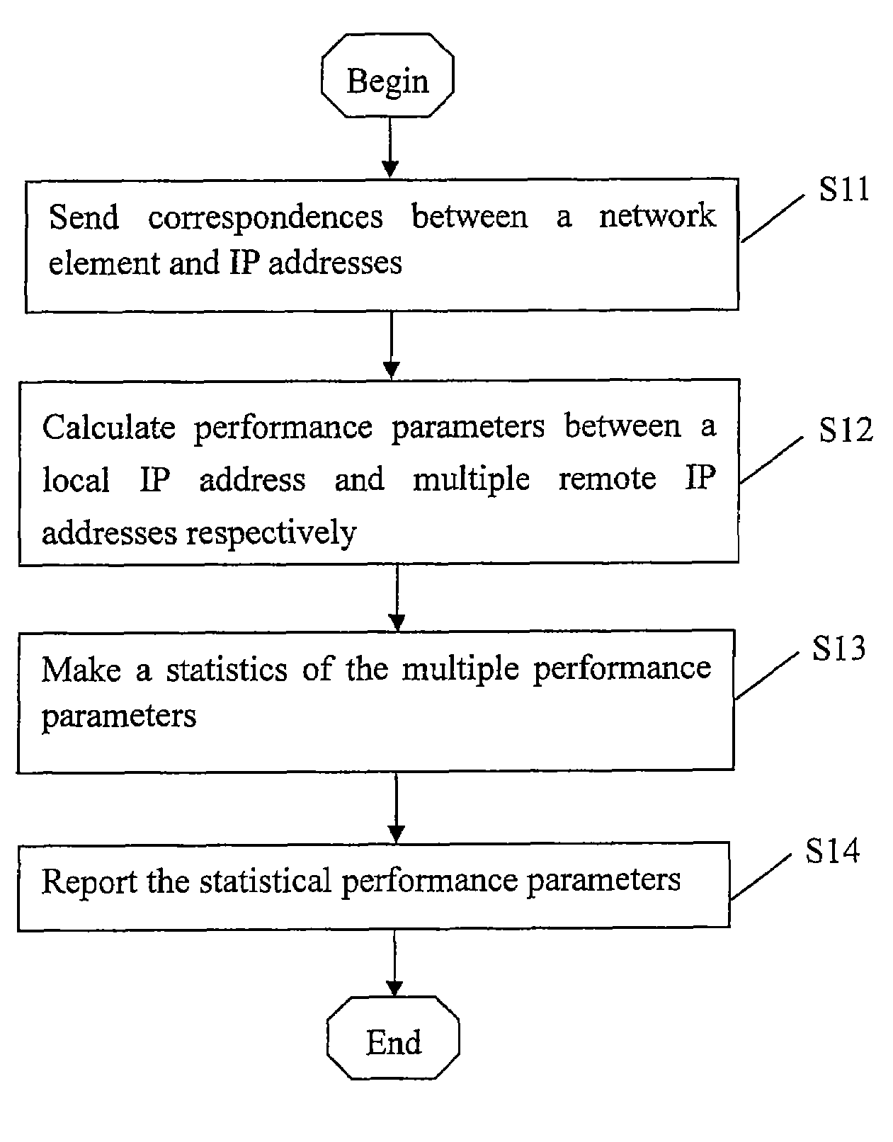
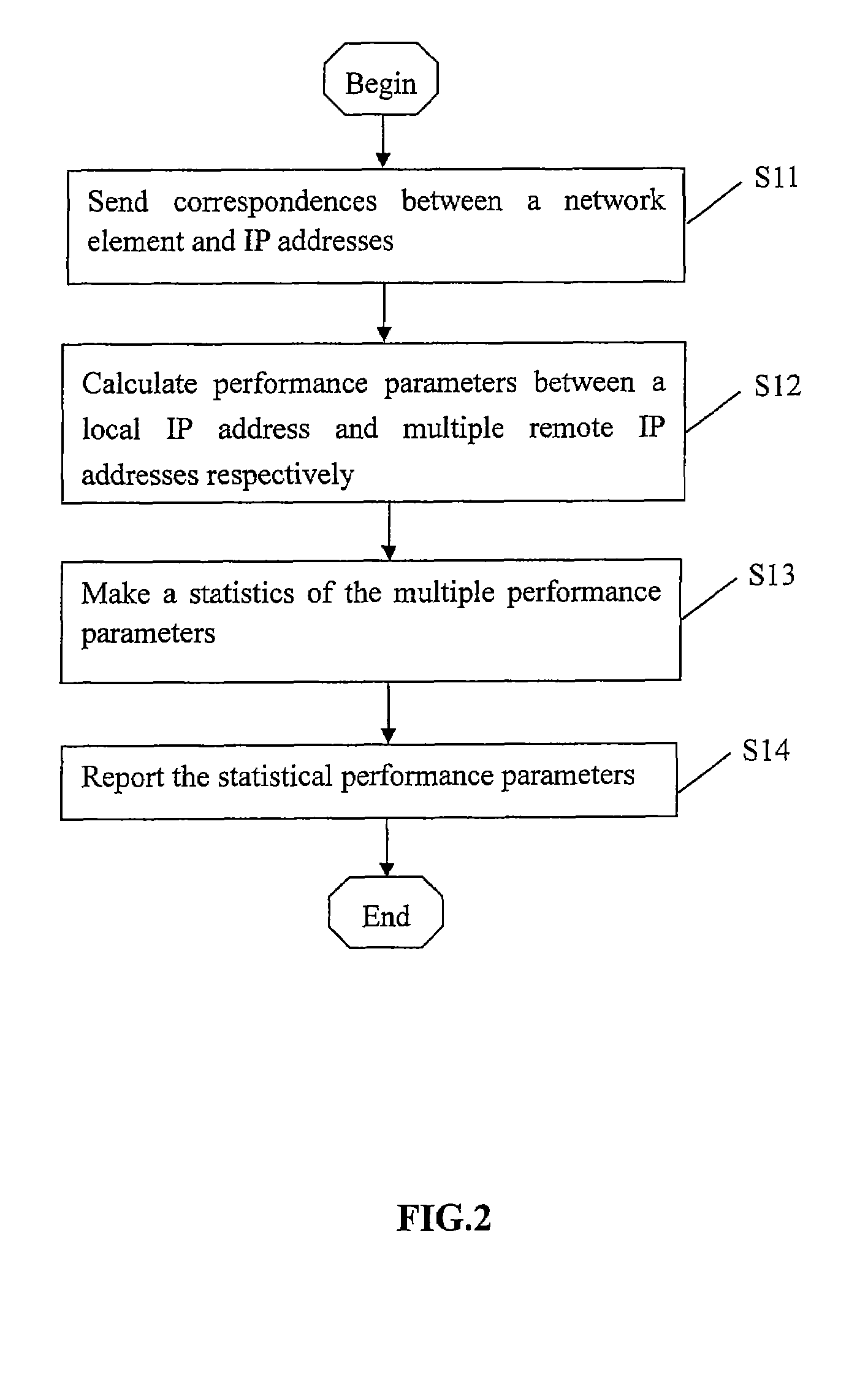
[0027]FIG. 2 is a flow chart of a method for monitoring network performance among network elements in an IP network according to an embodiment of the present invention. In an IP network such as an NGN, a network management device sends a message to each network element such as an MGW to request for a feedback of an IP address of an RTP port, the network element feeds back the IP address of the corresponding port, and the network management device establishes a correspondence between a remote network element and the IP address of the RTP port of the remote network element. In step S11, the network management device sends the correspondences between the remote MGW and a set of IP addresses thereof to the local MGW, and creates a statistical task of network performance. An example of creating a statistical task using commands is as follows:

CRE IPQOSTSK: TSKN=“beijing-guangzhou”

MU=IP...


PUM


Abstract

A method for monitoring network performance includes: sending correspondences between a remote network element and a plurality of IP addresses thereof from a network management device to a local network element; according to the correspondences, calculating performance parameters between the local IP address and the plurality of remote IP addresses respectively, by the local network element; making a statistics of the calculated performance parameters by the local network element. A network element for monitoring network performance, connected with a network management device and a remote network element, includes: a receiving unit, a performance parameter processing unit, a performance parameter statistics unit, and the transmitting unit. A network system for monitoring network performance is further provided. According to embodiments of this invention, the efficient measurement of network performance including IP QoS between each two MGWs of an IP network, RTP stream bandwidths, and the like, is realized, thus the message bandwidth of performance test can be saved and processing load of the network management device can be reduced.

Description

CROSS REFERENCE TO RELATED APPLICATIONS[0001]This application claims priority to Chinese Patent Application 200510121232.3 filed Dec. 22, 2005.FIELD OF THE INVENTION[0002]The present invention relates to network communication, and more particularly to a method, device and system for monitoring network performance.BACKGROUND OF THE INVENTION[0003]Transmitting data converted from voice signals via an IP network can greatly save transmission bandwidth and establishing time. At present, a Next Generation Network (NGN) and a WCDMA core network with R4 architecture are implemented gradually throughout the world. However, delay, jitter and packet loss occur frequently due to the speciality of IP network, which bring a great adverse effect on quality of voice. The monitoring of end-to-end Quality of Service (QoS) of a large-scale NGN and bandwidth of Real-time Transport Protocol (RTP) streams has become an important technical issue in the NGN.[0004]FIG. 1 is a schematic diagram of topology ...

Claims


Application Information

Patent Timeline
Patent Type & Authority Patents(United States)
IPC IPC(8): H04L12/26
CPCH04L41/142H04L43/062H04L43/0829H04L43/0852H04L43/16H04L41/044H04L43/087
Inventor ZOU, YONGHUANG, YUNTAO
Owner HUAWEI TECH CO LTD
Learn More