
Steel plate sprocket and method of producing same

a technology of steel plate and sprocket, which is applied in the direction of gear teeth, forging/hammering/pressing machines, manufacturing tools, etc., can solve the problems of damage or excessive wear of the chain that engages the sprocket, and achieve the effect of short delivery time and high added valu

Inactive Publication Date: 2009-12-22
TSUBAKIMOTO CHAIN CO +1
View PDF12 Cites 9 Cited by
  • Summary
  • Abstract
  • Description
  • Claims
  • Application Information

AI Technical Summary

Benefits of technology

The process ensures a reliable alignment of sprockets with chains, reduces production costs, and enhances quality by eliminating burrs and the need for finish machining, resulting in a high-value product that meets diverse user requirements with improved precision and reduced delivery time.

Problems solved by technology

Even when the tooth head is finished so that has a symmetric curvature, the process of turning, milling, or the like, can leave a burr at a tooth bottom or on a tooth side, which can cause damage or excessive wear to a chain that engages the sprocket.

Method used


Image

  • Steel plate sprocket and method of producing same
  • Steel plate sprocket and method of producing same
  • Steel plate sprocket and method of producing same

Examples


Embodiment Construction

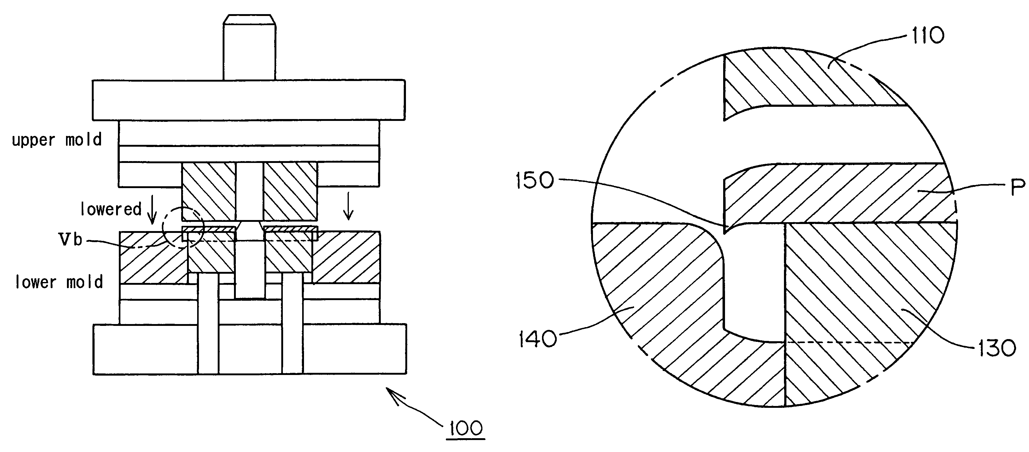
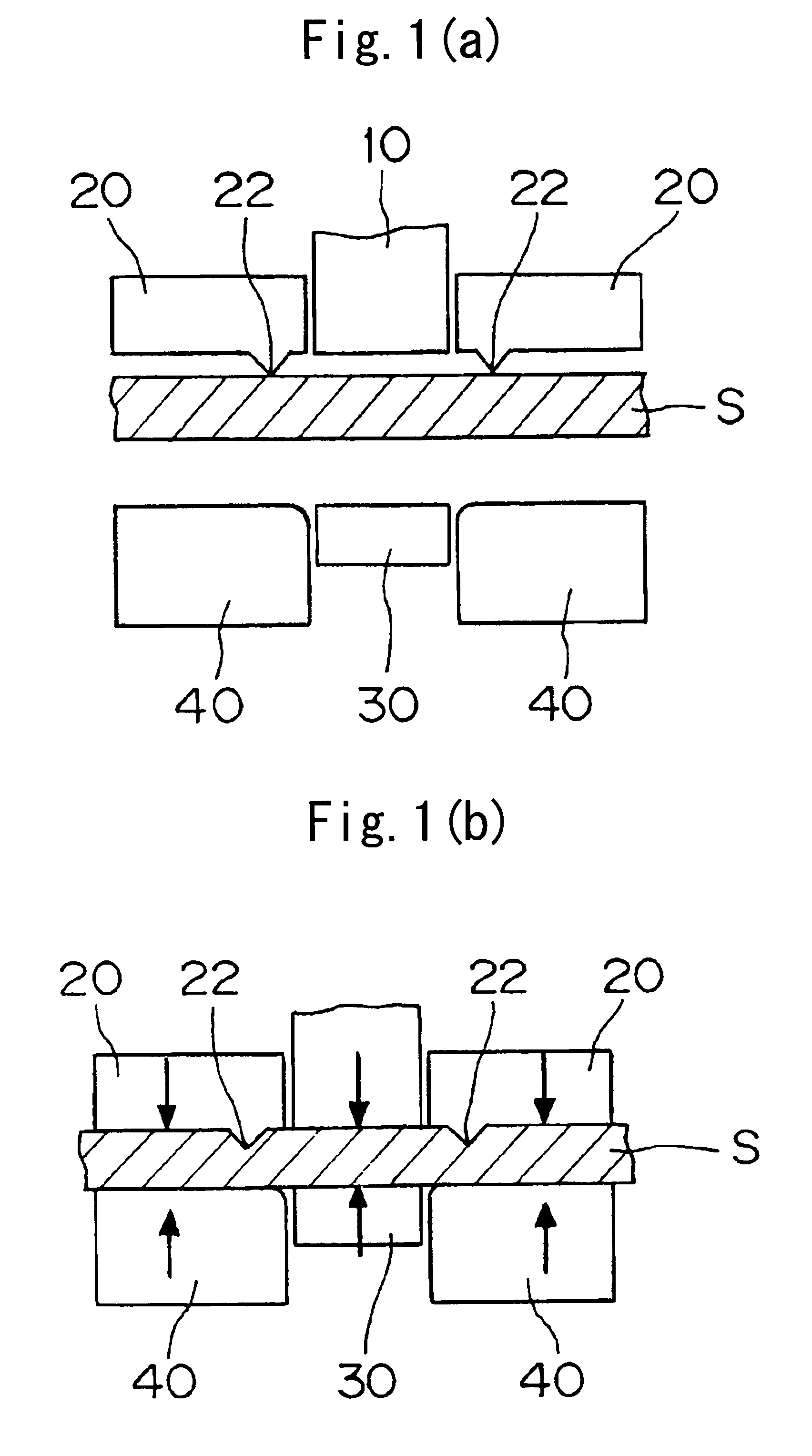
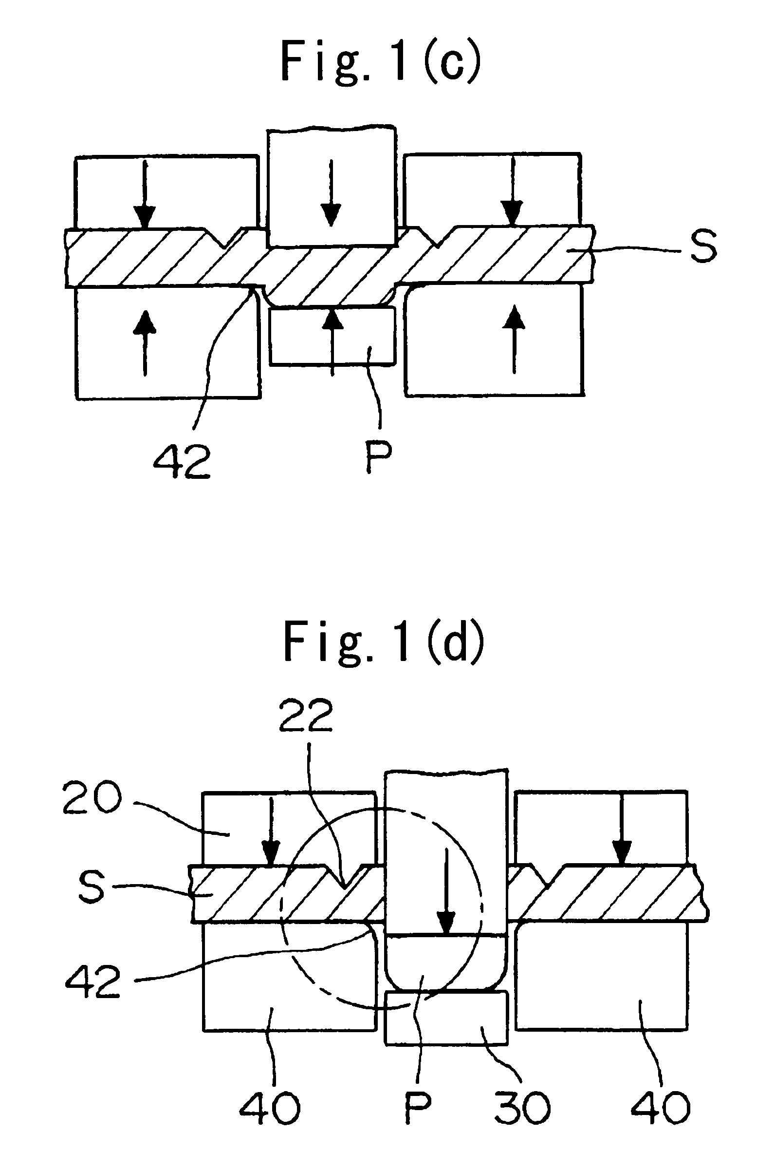
[0024]FIGS. 1(a) to 1(f) illustrate the progress of the fine blanking operation, which is the first step of the process according to the invention. The figures show the fine blanking of a steel plate sprocket.

[0025]As shown in FIG. 1(a), a steel plate S is passed through a metal mold for fine blanking. The metal mold comprises a punch 10 and a cooperating die 40, a back-up plate 20, opposed to the die 40 and having a knife edge-shaped V-ring 22, and a reverse punch backup 30 opposed to the punch 10.

[0026]As shown in FIG. 1(b), a lower mold part, comprising the reverse punch backup 30 and the die 40, is raised, and a pressing force is applied to the plate S. At this time, pressure is applied to the reverse punch backup 30 and the plate backup 20 by means of a hydraulic press (not shown). The knife edge-shaped V ring 22, which is provided on the plate backup 20 along the profile of the product, is pressed into the steel plate S. The steel plate S, which tends to expand in a direction ...


PUM

PropertyMeasurementUnit
heightaaaaaaaaaa
heightaaaaaaaaaa
shapeaaaaaaaaaa

Abstract

A sprocket is formed by fine-blanking a steel plate using a die having a cutting edge shaped to produce rounded edges on the back sides of the sprocket tooth heads, and protrusions on the front sides. Thereafter the edges of the front sides of the sprocket tooth heads are formed in a press so that the protrusions are removed, and the edges of the front sides of the sprocket tooth heads have a rounded cross-sectional shape substantially the same as that of the edges of the front sides.

Description

CROSS-REFERENCE TO RELATED APPLICATION[0001]This application claims priority on the basis of Japanese patent application 2006-042914, filed Feb. 20, 2006. The disclosure of Japanese application 2006-042914 is hereby incorporated by reference.FIELD OF THE INVENTION[0002]This invention relates generally to the formation of machine elements, and more particularly to the formation of a steel plate sprocket.BACKGROUND OF THE INVENTION[0003]Most internal combustion engines include a timing transmission in which an endless chain delivers power from a driving sprocket to a driven sprocket. The sprockets have been typically produced by sinter molding of a powder alloy or by skiving bulk steel. However, more recently, because of diverse user requirements, such as improvement of quality and production, cost reduction, short delivery time, and the like, sprockets have been produced by fine blanking of steel plate. Such a process is described in Japanese Laid-Open Patent Publication No. 2002-144...

Claims


Application Information

Patent Timeline
Patent Type & Authority Patents(United States)
IPC IPC(8): B21D53/28B21J13/00
CPCB21D28/16B21D53/28Y10T409/10Y10T29/49472Y10T29/49474
Inventor UEKI, TAKASHIYAMAMOTO, KATSUHIRO
Owner TSUBAKIMOTO CHAIN CO
Learn More