
Frequency stabilized laser source

a laser source and frequency stabilizer technology, applied in the direction of laser details, optical resonator shape and construction, electrical equipment, etc., can solve the problems of green noise, manifested green noise, green noise, etc., to facilitate stability and tuning of lasers, reduce costs, and improve production efficiency

Active Publication Date: 2009-12-15
COBOLT
View PDF7 Cites 1 Cited by
  • Summary
  • Abstract
  • Description
  • Claims
  • Application Information

AI Technical Summary

Benefits of technology

"The present invention provides an improved stability in an intracavity frequency-converted diode-pumped solid-state laser (DPSSL) by optimizing design considerations. The laser utilizes a gain material with anisotropic gain, which helps to stabilize the polarization state in the laser cavity. The laser also employs a folded geometry with a folding mirror that provides polarization discrimination. The laser arrangement should have a high degree of stability and easy assembly and alignment. The invention also addresses the issue of non-uniform losses in the nonlinear crystal and provides a solution to balance the nonlinear losses. The laser design is suitable for generating a wide range of wavelengths and is efficient in generating green light. The use of an anisotropic gain material and a folded geometry further enhances the stability and tuning of the laser."

Problems solved by technology

Another reason is that intracavity frequency doubling of a fundamental laser signal having a plurality of longitudinal modes typically leads to the so-called green problem, or “green noise”.
Green-noise is manifested by large and irregular intensity variations in the output from the laser due to gain competition between adjacent laser modes.
Such intensity variations are normally highly undesired.
Stability problems may also be caused by spatial hole-burning in the laser gain material.
Mode-hops to such competing mode may be the undesired result.
Moreover, the prior art has not adequately addressed the situation where a periodically poled nonlinear crystal is employed for frequency conversion within the resonant cavity of the laser.
For example, when using quasi phase-matched frequency conversion in a periodically poled crystal located within the resonant cavity, an ordinary ray and an extraordinary ray will always suffer different losses due to the fact that quasi phase-matching is a Type-I process in which waves of the same polarization participate in the nonlinear process, thus leading to a nonlinear loss for only one of these rays.

Method used


Image

  • Frequency stabilized laser source
  • Frequency stabilized laser source
  • Frequency stabilized laser source

Examples


Embodiment Construction

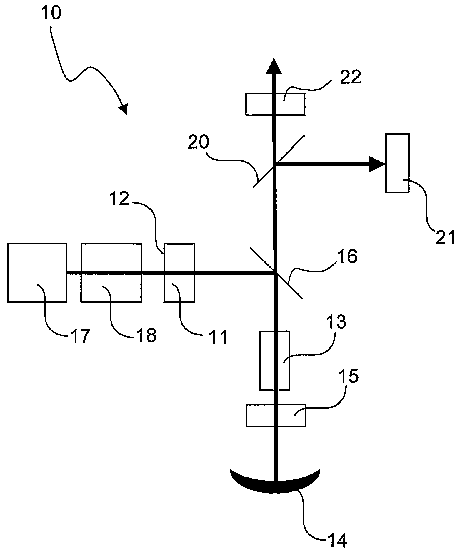
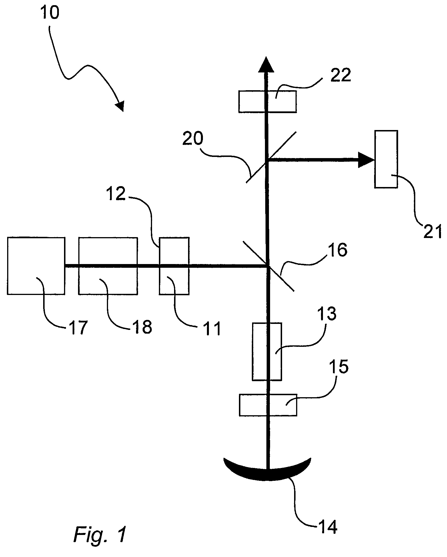
[0031]In order to fully appreciate the principles behind the present invention, an understanding of the Lyot-type filter in connection with a frequency-converted DPSSL is useful. By way of introduction, the Lyot-filter will be briefly explained.

[0032]The principle behind the Lyot filter is based upon polarization rotation (or alteration or “depolarization”) by launching the light through a birefringent material. Dispersion in the birefringent material results in different polarization alterations for different wavelengths of incident light. For a Lyot filter located within the resonant cavity of a laser, this means that different longitudinal modes of the laser will experience different polarization changes due to the propagation through the birefringent material. Also included in the Lyot filter arrangement is some kind of polarizer, which will introduce different losses depending on the polarization state of incident light. Typically, a polarizer will pass substantially all light ...


PUM


Abstract

A laser arrangement is provided, in which a Lyot filter arrangement is operative to effect single mode operation. The birefringent element of the Lyot filter arrangement has a cavity folding mirror on one side thereof and a polarizing element on another side thereof, such that the free spectral range of the Lyot filter is improved. Preferably, the Lyot filter arrangement and the laser gain material are located in different branches of the folded cavity.

Description

TECHNICAL FIELD[0001]The present invention relates to frequency stabilized laser sources in which frequency conversion is performed within the resonant optical cavity of the laser. More particularly, the present invention relates to such laser sources which are frequency stabilized by means of a Lyot filter arrangement.BACKGROUND AND RELATED ART[0002]Diode-pumped solid-state lasers (DPSSL) with emission wavelengths in the visible range of the electromagnetic spectrum are well known laser systems. Products based on this general technology are widely used in material processing, bioanalysis, medicine, holography, spectroscopy, printing, graphics and entertainment, to name some applications.[0003]A DPSSL with emission wavelengths in the visible generally comprises a DPSSL operating at a wavelength between 800 and 1400 nm, this emission being frequency converted (such as frequency doubled) to a wavelength between 400 and 700 nm. The frequency conversion is performed in a nonlinear optic...

Claims


Application Information

Patent Timeline
Patent Type & Authority Patents(United States)
IPC IPC(8): H01S3/10H01S3/08
CPCH01S3/109H01S3/08031H01S3/0815H01S3/1673H01S3/1611H01S3/09415H01S3/08
Inventor HELLSTROM, JONASKARLSSON, GUNNARKARLSSON, HAKAN
Owner COBOLT
Learn More