
Flexible, suspension, and head gimbal assembly with piezoelectric layer units addressable by a voltage

a piezoelectric layer unit and gimbal technology, applied in the direction of recording information storage, maintaining the alignment of the head carrier, instruments, etc., can solve the problem of difficult to adjust the float height of the magnetic head from the hard disk, and achieve the effect of suppressing reaction forces, high speed, and high precision

Inactive Publication Date: 2009-12-08
TDK CORPARATION
View PDF17 Cites 8 Cited by
  • Summary
  • Abstract
  • Description
  • Claims
  • Application Information

AI Technical Summary

Benefits of technology

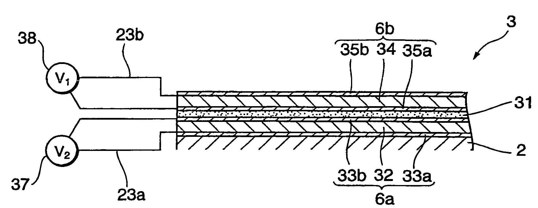
The present invention provides a flexure, suspension, and head gimbal assembly that can perform tracking adjustment with high precision and at high speed, and can adjust the float height of magnetic heads from the hard disk. The flexure includes a main body on which a head slider is mounted, and a pair of piezoelectric layer units that can be adjusted individually to change the shape of the piezoelectric layer units and thus the head slider in three directions of pitch, roll, and yaw. This allows for precise tracking adjustment and proper adjustment of the float height of the magnetic head. The suspension and head gimbal assembly according to this invention can be provided with the flexure, which allows for swanning of the head slider in three directions. The head slider is attached to the main body at the center of gravity of a side face of the head slider, which suppresses reaction forces from being applied to the suspension when the head slider is swung.

Problems solved by technology

However, for the mechanism described in Japanese Laid-Open Patent Application No. 2002-203384, though it is possible to perform the tracking adjustment with a high precision and at a high speed by utilizing the piezoelectric material, it is difficult to adjust the float height of magnetic heads from the hard disk.

Method used


Image

  • Flexible, suspension, and head gimbal assembly with piezoelectric layer units addressable by a voltage
  • Flexible, suspension, and head gimbal assembly with piezoelectric layer units addressable by a voltage
  • Flexible, suspension, and head gimbal assembly with piezoelectric layer units addressable by a voltage

Examples


first embodiment

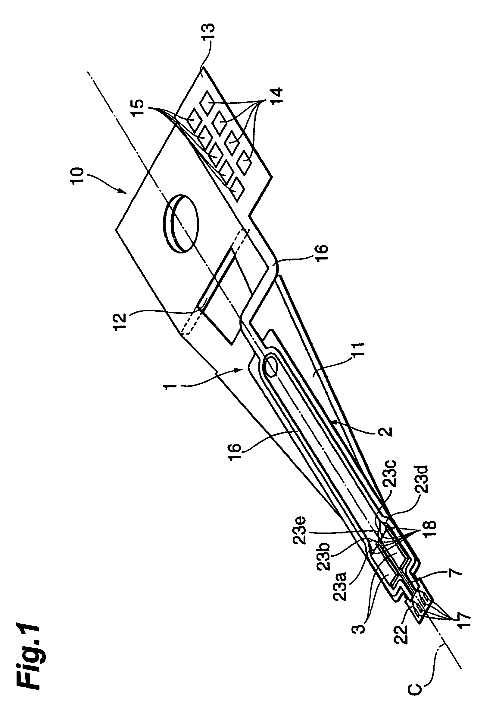
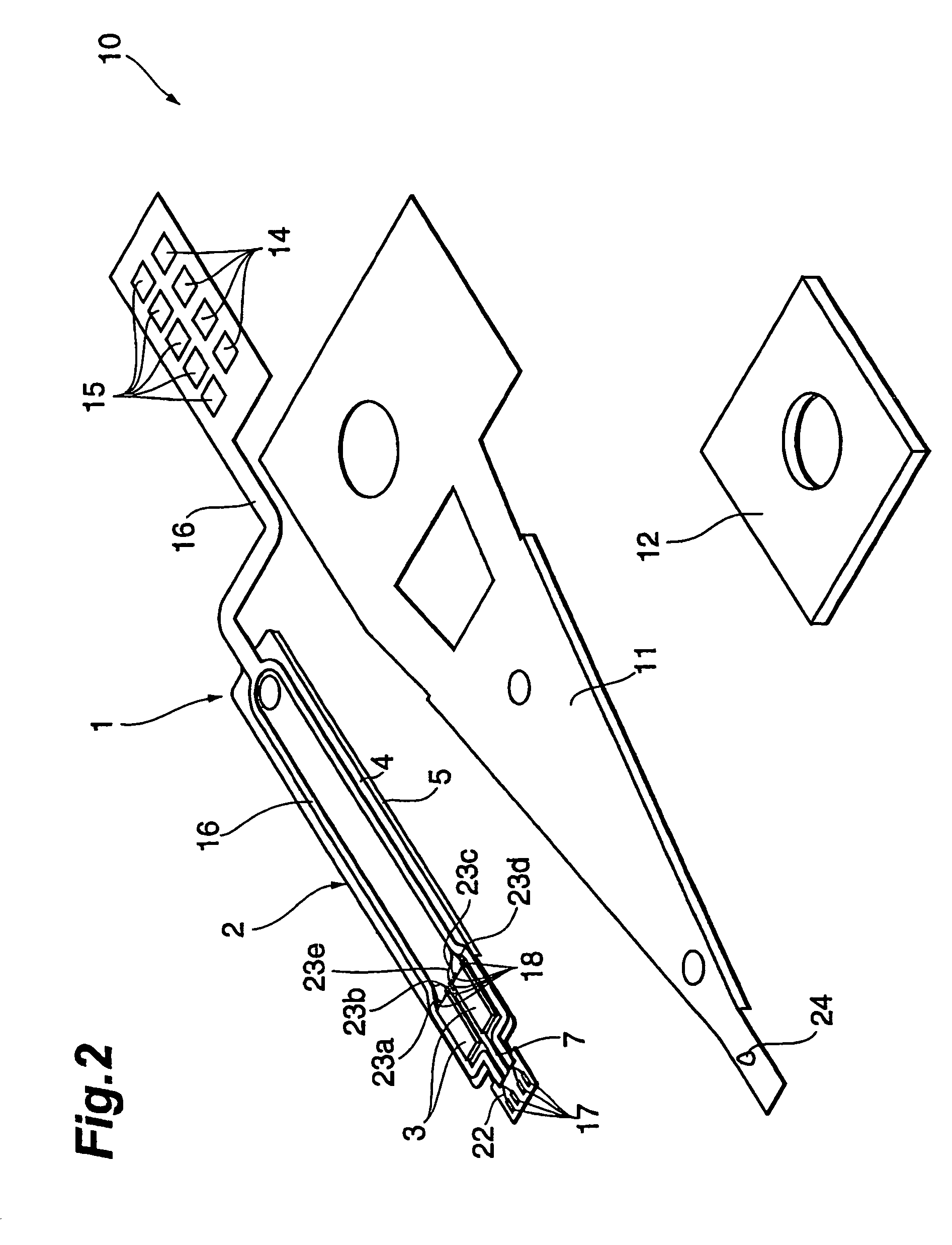
[0026]FIG. 1 is a view showing a suspension provided with a flexure according to an embodiment of the present invention. FIG. 2 is an exploded perspective view of the suspension shown in FIG. 1. FIG. 3 is a view showing a head gimbal assembly according to this embodiment.

[0027]As shown in FIGS. 1-3, suspension 10 for suspending head slider 20 is constituted mainly by arm member 11, base plate 12, and flexure 1. As shown in FIG. 3, head gimbal assembly 30 is constituted by mounting head slider 20 on suspension 10. Head slider 20 is provided with thin-film magnetic head 21 that performs a recording and / or reproduction with respect to a hard disk (recording medium) that is not shown in the drawing.

[0028]Arm member 11 of suspension 10 is a thin plate made of metal such as stainless steel and is an elastic body that bends in the direction perpendicular to its surface. Base plate 12 is provided on the base side of arm member 11. Furthermore, base plate 12 is attached to a rotation drive d...


PUM

PropertyMeasurementUnit
gravityaaaaaaaaaa
magneticaaaaaaaaaa
recording densityaaaaaaaaaa

Abstract

A flexure is provided with a main body on which a wire for energizing a head slider is disposed. Head slider is mounted at the front end of the flexure. Two piezoelectric layer units, each including layered piezoelectric elements, are disposed so that two of the units sandwich a line that extends from head slider to a base portion of an arm member. A voltage can be applied individually to each of the piezoelectric elements. The shape of the piezoelectric layer units are changed by adjusting the voltage applied to each of the piezoelectric elements, thereby moving head slider freely.

Description

RELATED APPLICATION[0001]Japanese Patent Application No. 2003-310,403 filed on Sep. 2, 2003, from which priority is claimed, is hereby incorporated herein by reference in its entirety.BACKGROUND OF THE INVENTION[0002]1. Field of the Invention[0003]The present invention relates to a flexure, a suspension, and a head gimbal assembly that may be applied to a hard disk drive, for example.[0004]2. Description of Related Art[0005]Head sliders having a thin-film magnetic head that records and / or reproduces magnetic information onto / from a hard disk (recording medium) constitute head gimbal assemblies by being attached to a suspension that is connected to a voice coil motor of a hard disk drive. The head sliders of the head gimbal assemblies float above hard disks in hard disk drives with a small gap therebetween, and record and / or reproduce magnetic information onto / from hard disks.[0006]Regarding such head sliders, as the recording density of hard disks increases, it has been demanded tha...

Claims


Application Information

Patent Timeline
Patent Type & Authority Patents(United States)
IPC IPC(8): G11B5/596G11B21/24G11B21/21G11B5/48G11B5/60
CPCG11B5/4853G11B5/6005G11B5/486G11B5/4873G11B5/5552
Inventor YAMAZAKI, HIROSHIMIYAZAKI, MASAHIRO
Owner TDK CORPARATION
Learn More