
Lens array, exposure device, and image forming apparatus

a technology which is applied in the field of exposure device and exposure array, can solve the problems of insufficient contrast between a bright section and a dark section of the exposure image, difficult to form the light absorbing layer, and deterioration of optical characteristics, so as to prevent the adverse effect of the fluctuation part on the optical characteristics, improve the resolution, and improve the contrast

Active Publication Date: 2009-12-08
OKI ELECTRIC IND CO LTD
View PDF10 Cites 0 Cited by
  • Summary
  • Abstract
  • Description
  • Claims
  • Application Information

AI Technical Summary

Benefits of technology

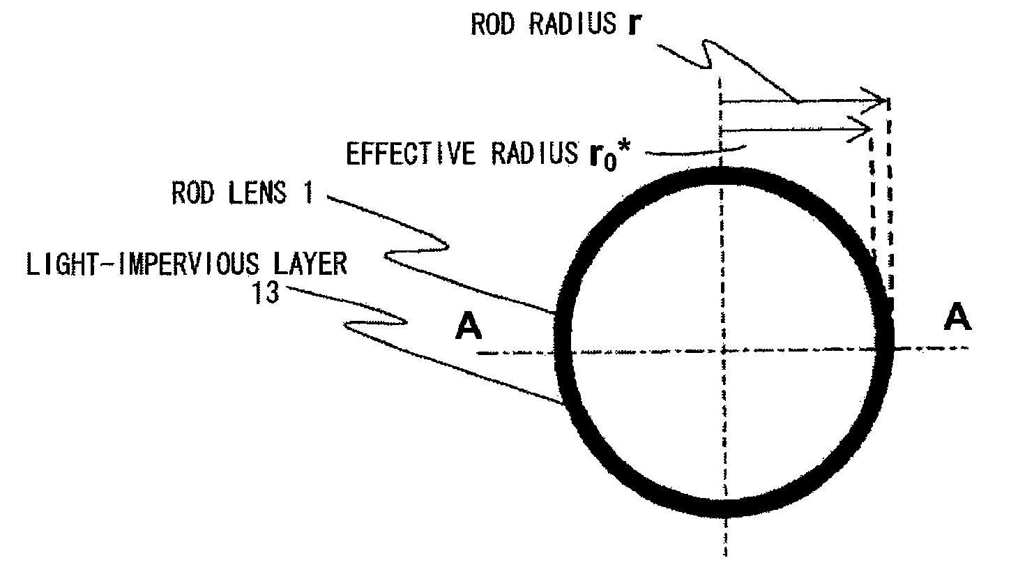
[0011]According to one example of the lens array in this invention, the fluctuation part in the refractive-index distribution formed at the outer periphery portion of the rod lens can be removed by setting the radius ratio r0 / r to 0.9 or smaller, thereby being able to prevent adverse effects of the fluctuation part on the optical characteristics. Therefore, clear images with high contrast can be achieved by applying the lens array according to this invention to the exposure device of the image forming apparatus in electrophotographic system. Furthermore, according to another example of the lens array in this invention, the light-impervious portion for blocking out the light beam from the luminous source is formed to the outer periphery of the rod lens, so that the light-impervious portion for blocking out the light beam functions as a type of an aperture stop to limit a scattered light, thereby achieving improvement in the resolution.
[0012]The lens array or the image forming apparatus according to this invention which determines a range of the radius r1 of the rod lens by calculation based on a desired value MTF, can resolve deterioration in image quality in terms of granular quality or a blur of a thin line in a halftone image, and the like, thereby resulting in good printing characteristics.

Problems solved by technology

However, in a case of formation of an exposure image at a high resolution on a photoreceptor by the aforementioned conventional technique, the exposure image has insufficient contrast between a bright section and a dark section.
By the method for forming the light absorbing layer described in Japanese Patent Laid-Open Publication No. 2003-114306, it is not easy to form the light absorbing layer having a predetermined micron-size thickness that uses a light absorbent such as a dye.
The resulting variation in thickness directly leads to deterioration in optical characteristics.

Method used


Image

  • Lens array, exposure device, and image forming apparatus
  • Lens array, exposure device, and image forming apparatus
  • Lens array, exposure device, and image forming apparatus

Examples


first embodiment

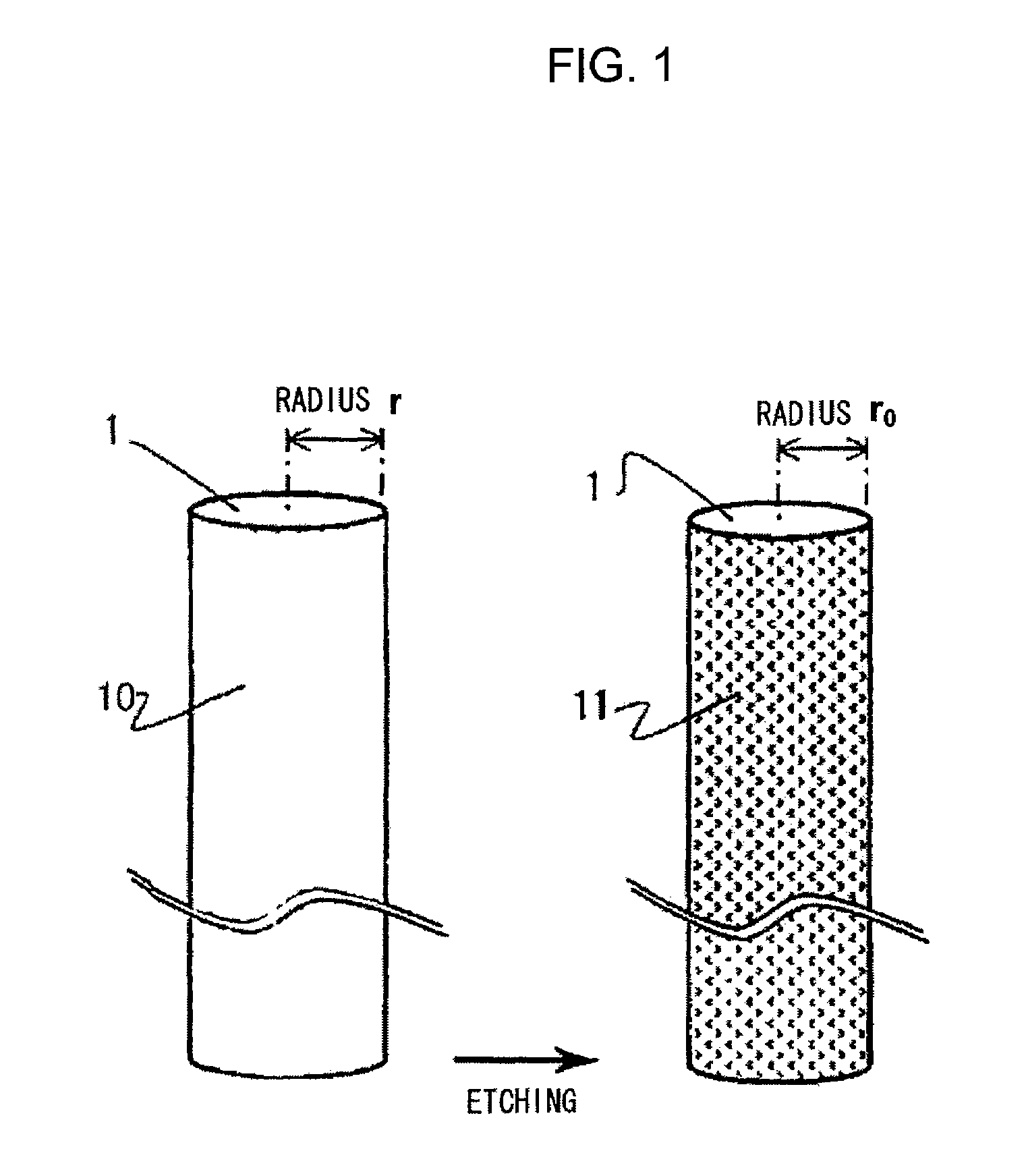
[0033]A lens array according to a first embodiment of this invention will be explained with reference to drawings. FIG. 1 is a perspective view showing a rod lens composing the lens array according to this embodiment. The lens array according to this embodiment adopts the rod lens that is formed by processing glass. For example, a rod lens made from glass is formed by a direct spinning method (continuous spinning method). In the method for forming the lens array, first, the glass is melted and shaped by the spinning method, thereby the glass being cut into a predetermined size. The glass fiber, which was cut out, is then subject to an ion-exchange process to form a refractive-index distribution, thereby becoming a rod lens 10 of radius r. The rod lens is then subject to an etching process to remove a portion of the outer periphery 10 to form a radius of r0. Subsequently, a side surface 11 of the rod lens is subject to a roughening process and coated with a black dye. The plurality o...

second embodiment

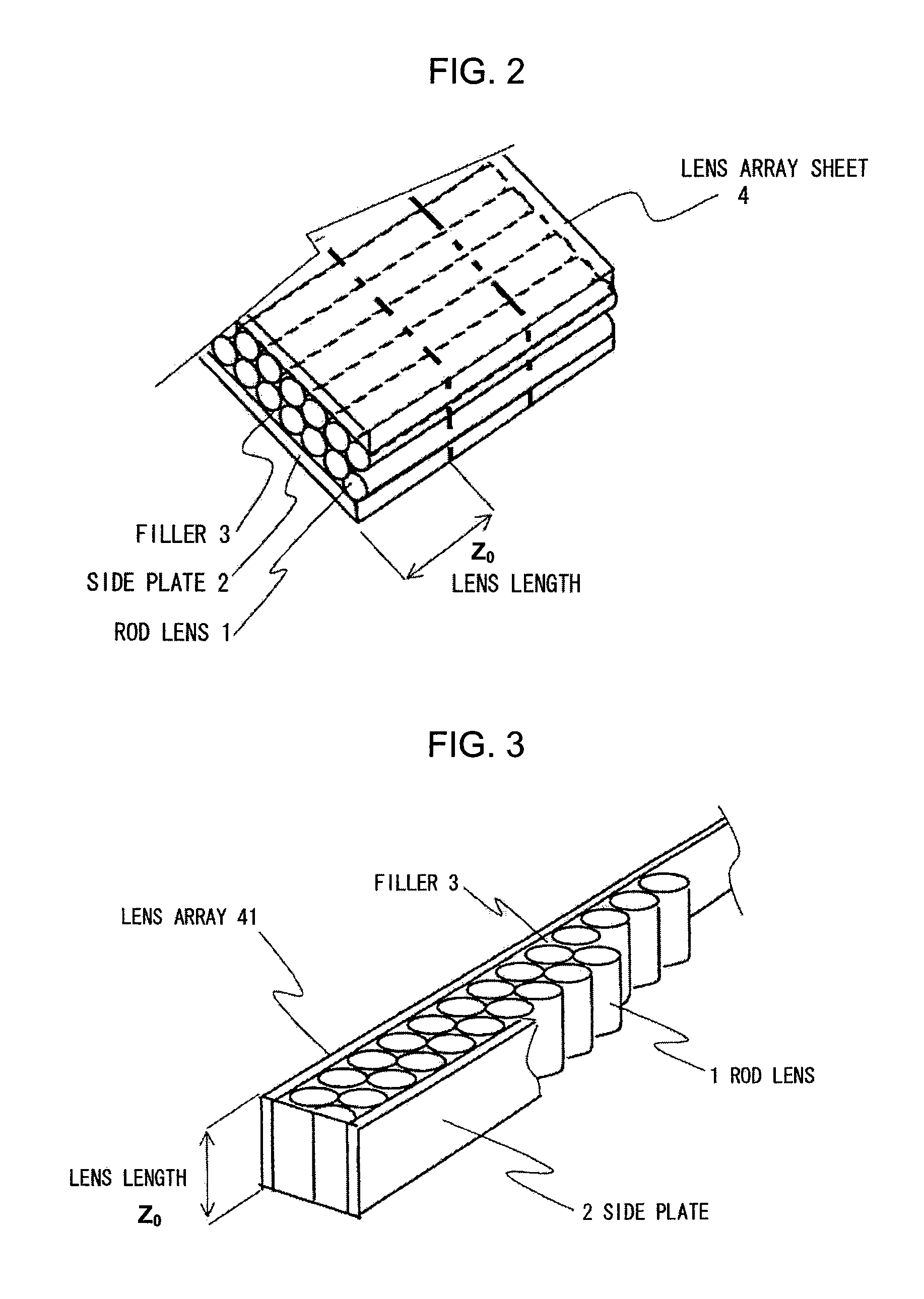
[0066]A structure of the lens array according to a second embodiment will be explained next. FIGS. 13 and 14 are schematic views of a lens array. In a manner similar to the lens array according to the first embodiment, the lens array is formed such that a refractive-index distribution is formed from a central axis to an outer periphery, in which the rod lenses 1 having been subject to the process for making the side surfaces thereof absorb the light beam from the luminous source are arrayed in one or more lines between two side plates 2. The filler 3 is filled into gaps and hardened to form the lens array.

[0067]The distances Lo between the luminous light source and the one end of rod lens and Li, the distance from the imaging surface to a second end of the rod lens in FIG. 14 are adjusted to set Li=Lo=Lf on the condition that a focal length of the lens array 41 is set to be Lf. A distance TC is a conjugation length of the lens array 41, which is a distance between a surface of an ob...

third embodiment

[0084]A structure of the lens array according to the third embodiment will be described next. The third embodiment has the same structure as that of the second embodiment in that there is such a relation as expressed by the following Equation 3 between the effective radius r1 [mm] of a portion of the rod lens 1, through which the light beam from the luminous source passes, and the conjugation length TC [mm] which is a distance between the object face of the lens array 41, as shown in drawings, and the imaging surface.

r1≦0.015 TC+0.113  [Equation 3]

[0085]Furthermore, with respect to the conjugation length TC [mm] in the lens array 41, there is such a relation as expressed by the following Equation 6.

9.100≦TC≦15.100  [Equation 6]

[0086]The exposure device and the image forming apparatus according to this embodiment have the same structure as those of the second embodiment in that there is such a relation as expressed by Equation 7 between the effective radius r1 of the rod lens 1 as sh...


PUM


Abstract

A lens array has a plurality of rod lenses with optical axes in parallel with one another, in which the rod lens has a refractive-index distribution in a radial direction. The lens array has a radius ratio r0 / r set to 0.9 or smaller, in which a radius r of the rod lens is set as the radius of the rod lens when the refractive-index distribution is formed, and in which a radius r0 of the rod lens is set as the radius of the rod lens when all or part of an outer periphery of the rod lens is removed after formation of the refractive-index distribution.

Description

BACKGROUND OF THE INVENTION[0001]This invention relates to a lens array used for an image transmitter such as, e.g., an electronic printer, a facsimile machine, and a scanner, to an exposure device adopting the lens array, and to an image forming apparatus furnished with the exposure device.[0002]Lens arrays (or rod lens arrays) in which a plurality of minute rod lenses in a cylindrical shape are arrayed are used as lens for an image transmitter built into an apparatus such as, e.g., an electronic printer, a facsimile machine, and a scanner. A rod lens is an optical lens made of a cylindrical-shaped resin or glass material with a refractive-index distribution in a radial direction. A lens array is an optical component in which the plurality of rod lenses are arrayed and unified, and is used as one part of an image sensor of a photocopier, the scanner, or the like. The lens array is also used as an exposure device forming an exposure image on a photoreceptor at a high resolution in c...

Claims


Application Information

Patent Timeline
Patent Type & Authority Patents(United States)
IPC IPC(8): G02B3/00G02B9/00
CPCG02B3/0006G02B3/0056
Inventor YAMAMURA, AKIHIRO
Owner OKI ELECTRIC IND CO LTD
Learn More