
Pulse-width modulation of pulse-code modulated signals at selectable or dynamically varying sample rates

a pulse-code modulation and sample rate technology, applied in the field of signal conversion, can solve problems such as wide-band noise, and achieve the effect of reducing the transients of the output pwm signal

Active Publication Date: 2009-12-01
TEXAS INSTR INC
View PDF9 Cites 8 Cited by
  • Summary
  • Abstract
  • Description
  • Claims
  • Application Information

AI Technical Summary

Benefits of technology

Enables flexible PWM period selection to reduce interference and implement spread-spectrum modulation, minimizing transients and noise in the output signal, even with abrupt changes in the PWM period.

Problems solved by technology

However, these selectable or dynamically varying PWM periods are, in general, not compatible with maintaining the PWM period only at integer multiples of the master PWM clock period.
In addition, abrupt or dynamic changes in the PWM period generally produce wide-band noise, including substantial noise energy in the audio band.

Method used


Image

  • Pulse-width modulation of pulse-code modulated signals at selectable or dynamically varying sample rates
  • Pulse-width modulation of pulse-code modulated signals at selectable or dynamically varying sample rates
  • Pulse-width modulation of pulse-code modulated signals at selectable or dynamically varying sample rates

Examples


Embodiment Construction

[0026]The present invention will be described in connection with its preferred embodiment, namely as implemented into a digital system having audio functionality, specifically a digital audio receiver in the described example in this specification. However, it is contemplated that the modulation function and method of this invention will be useful and beneficial in a wide range of system applications. These system applications can include any system in which processed digital signals are to be converted into a pulse-width modulated form, for example to actuate a physical device such as a speaker, motor, or other mechanical device. Accordingly, it is to be understood that the following description is provided by way of example only, and is not intended to limit the true scope of this invention as claimed.

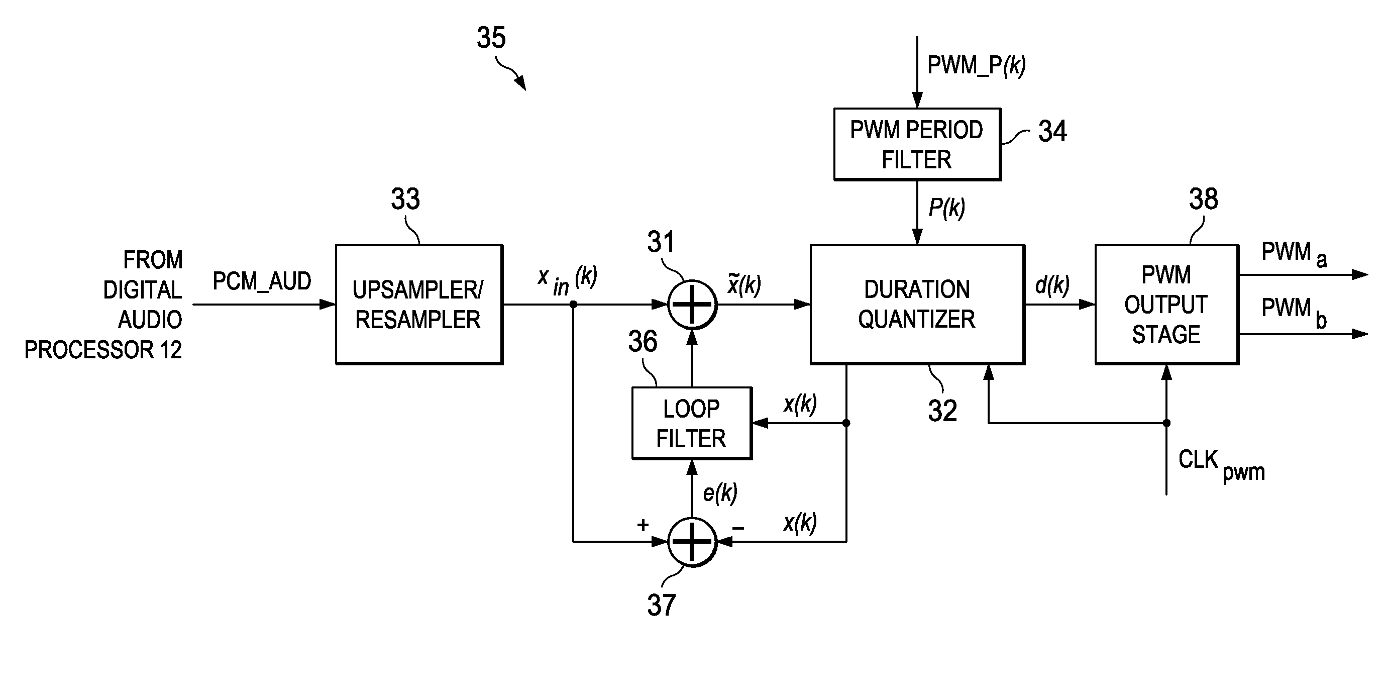
[0027]FIG. 3 illustrates an example of the construction of audio processing circuitry in digital audio receiver 10 according to the preferred embodiment of the invention. Receiver 10...


PUM


Abstract

Digital audio circuitry including modulation circuitry (35; 135) for generating a pulse-width modulated (PWM) signal from processed pulse-code modulated (PCM) audio signals. The modulation circuitry includes a duration quantizer function (32) that generates a sequence of duration values d(k) from received PCM samples, quantized to integer multiples of periods of a master PWM clock (CLKpwm). The duration quantizer function also produces a feedback PCM value x(k) from each quantized duration value d(k) that is applied to a loop filter (36), the output of which modifies the received PCM sample stream to suppress quantization noise. Transient effects caused by modulation or abrupt changes in the desired PWM period are suppressed by digitally filtering (34; 134) the PWM period sample stream.

Description

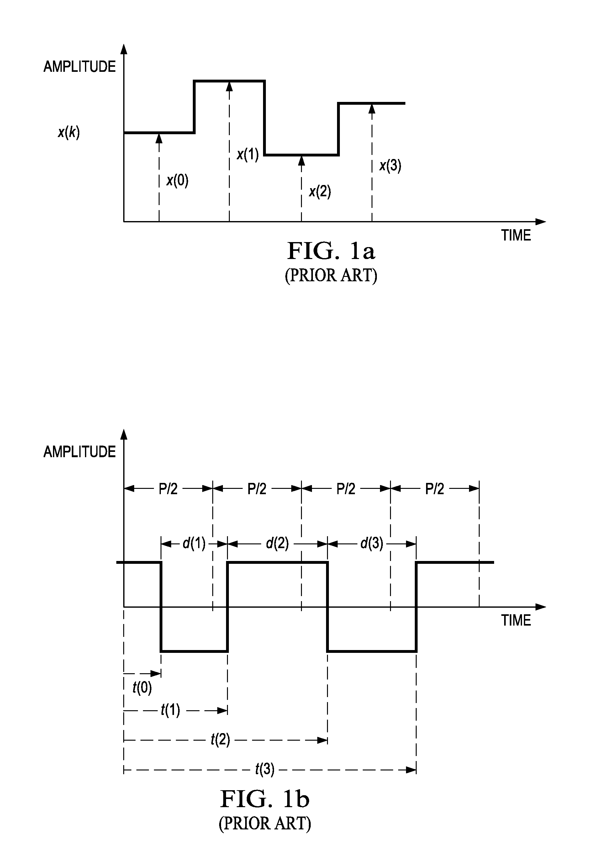
CROSS-REFERENCE TO RELATED APPLICATIONS[0001]This application claims priority, under 35 U.S.C. §119(e), of Provisional Application No. 60 / 940,844, filed May 30, 2007, incorporated herein by this reference.STATEMENT REGARDING FEDERALLY SPONSORED RESEARCH OR DEVELOPMENT[0002]Not applicable.BACKGROUND OF THE INVENTION[0003]This invention is in the field of signal conversion, and is more specifically directed to the pulse-width modulation (PWM) of pulse-code modulated (PCM) signals.[0004]As is well known in the communications art, information can be communicated by way of modulations in an electrical signal. Many classes of modulation approaches are well-known in the art, including amplitude modulation, frequency modulation, and phase modulation. In the digital signal domain, pulse-code modulation (PCM) refers to amplitude modulation in which the amplitude of each pulse of a periodic signal train is quantized into one of a number of available amplitude levels, each available amplitude l...

Claims


Application Information

Patent Timeline
Patent Type & Authority Patents(United States)
IPC IPC(8): H03M5/08
CPCH03M5/08G10L19/10
Inventor RISBO, LARS
Owner TEXAS INSTR INC
Learn More