
Metal fiber brush interface conditioning

a technology of metal fiber brushes and interfaces, applied in current collectors, dynamo-electric machines, electrical equipment, etc., can solve the problems of reducing the life of brushes, so as to increase the current density and/or sliding speed of brushes, and reduce wear. the effect of the rate of deterioration

Active Publication Date: 2009-11-24
ALEXSAVA HLDG
View PDF32 Cites 37 Cited by
  • Summary
  • Abstract
  • Description
  • Claims
  • Application Information

AI Technical Summary

Benefits of technology

[0016]A further object of the present invention is to reduce the need for adsorbed moisture in the successful operation of electrical metal fiber brushes.
[0027]According to another aspect of the present invention, there is provided an electrical brush, including at least one conductive element; and at least one conditioning material coated on the at least one conductive element with a thickness SC on the conductive element in a range of from 0.05 μm≦SC≦10 μm, the conditioning material having a composition and being deposited in a manner such as to eliminate contact spots.

Problems solved by technology

Further, in the course of sliding and incidentally mechanically wearing, monolithic brushes deposit a thin, electrically conductive graphitic surface film on the substrate that is apparently composed of consolidated wear debris.
However, on account of the greater mechanical stiffness of the monolithic brushes, the monolithic brushes do not slide successfully at velocities above, for example, 40 m / sec.
Commercial monolithic brushes sliding on copper or copper alloys typically do not employ special measures to protect the substrate from oxidation because the graphitic film that is deposited offers adequate protection.
On the down-side, often the presence of a well-seasoned graphitic layer is needed for proper functioning of commercial monolithic brushes, and as it happens, such layers have a tendency to deteriorate in periods of rest and under any number of other influences.
As a result, monolithic brushes may perform erratically and pose problems in high-tech applications, e.g. in the main motor-generator of submarines.
This is for the reason that graphite is a layer-type crystal whose shearability depends on the presence of water and which in dry conditions is brittle and abrasive.

Method used


Image

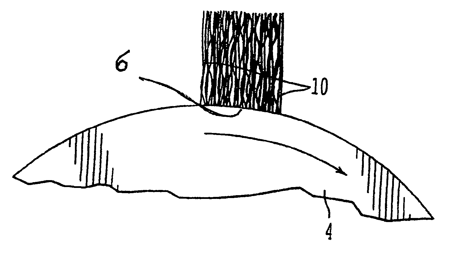
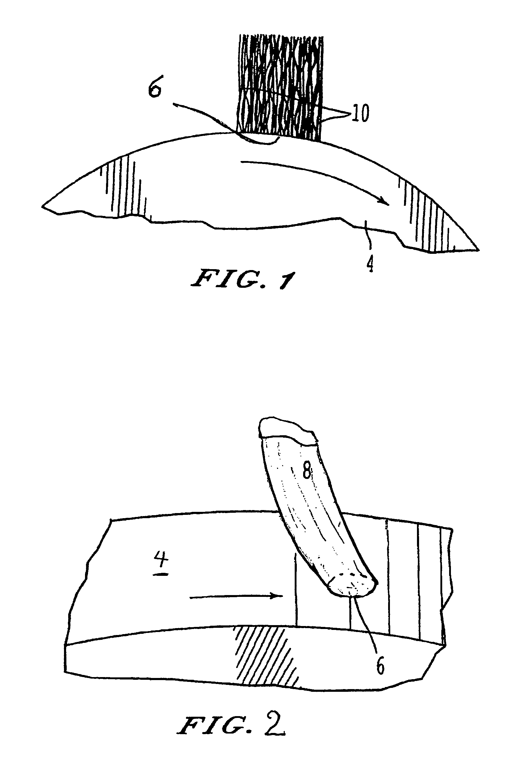
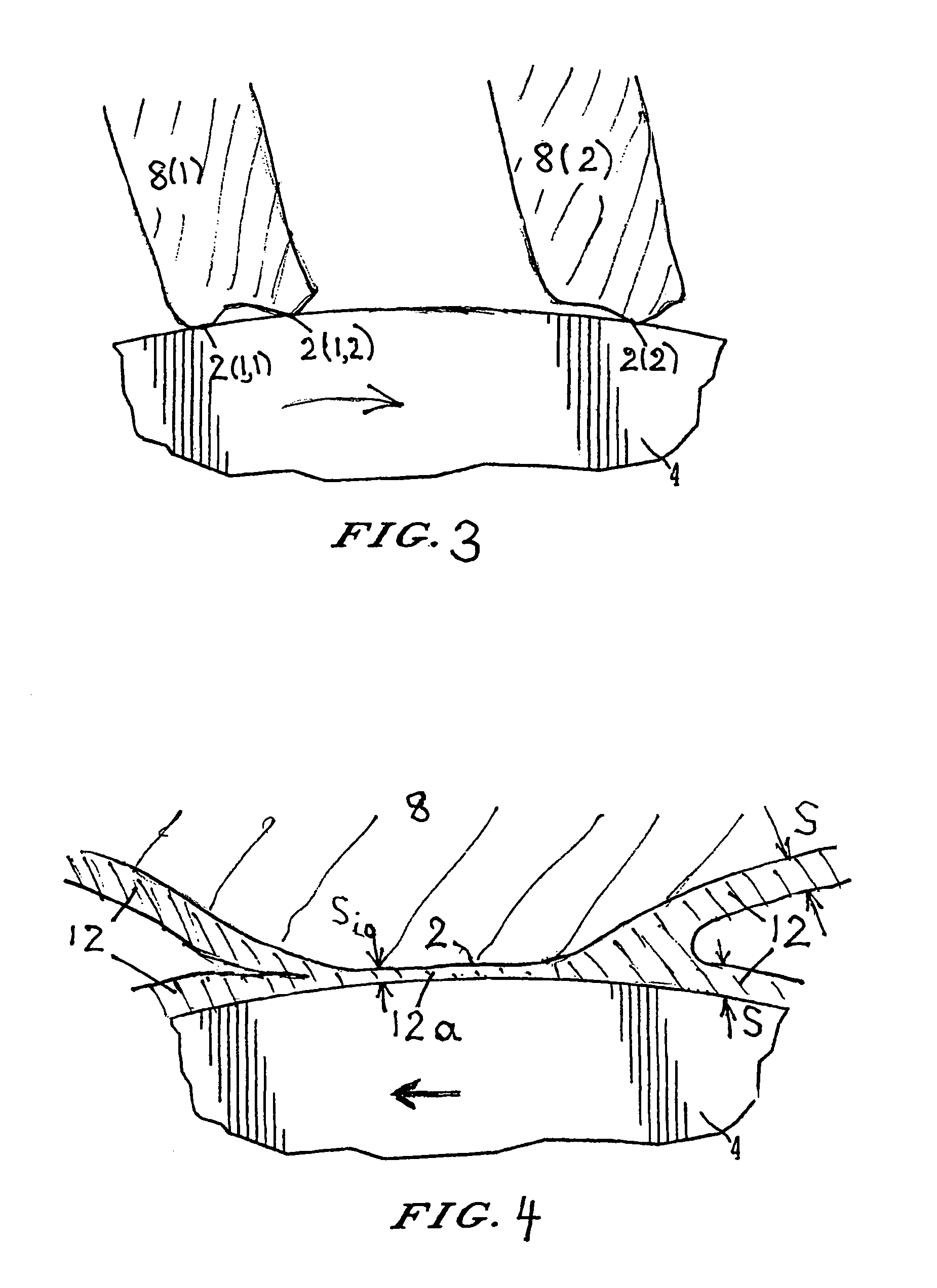
  • Metal fiber brush interface conditioning
  • Metal fiber brush interface conditioning
  • Metal fiber brush interface conditioning

Examples


examples

[0206]Experiments on a range of materials to-date have shown that successful conditioning film materials may on occasion (but do not typically) lower the friction coefficient, typically will reduce the wear rate, and can significantly reduce or eliminate brush polarity effects. Table 1 in FIGS. 7A to 7C presents relevant data. As an example, in an experiment extending over several days, two metal fiber brushes with an approximately SC=1.4 μm thick surface layer on the interior fiber surfaces of “Tip Top” glass cleaner, exhibited average dimensionless wear rates of 4×10⁻¹¹ and 5×10⁻¹¹ in the open atmosphere at v=16 m / sec sliding speed and current density j=20 to 40 A / cm2. The friction coefficient was μ≅0.4, and the film resistivity ranged about σF≈2.6×10⁻¹² Ωm2 and σF≈5×10⁻¹² Ωm2 on the positive and negative brush, respectively.

[0207]Brushes in Table 1 (see FIGS. 7A to 7C) marked as not sensitive to humidity and temperature are those whose film resistivity and friction changed only b...


PUM


Abstract

An electrical brush having at least one conductive element and at least one conditioning material coated on the at least one conductive element wherein the conditioning material has a composition and thickness on the conductive element such that, as deposited on a moving contact surface in the course of brush operation, the conditioning material can have an average film thickness S<˜1 μm so that current can be conducted by means of electron tunneling through a film thickness of the deposited conditioning material of Si≦12 nm thickness over a fractional area fC, greater than 0.01 of a foot print of the conductive element in a current conductive area.

Description

CROSS-REFERENCE TO RELATED APPLICATIONS[0001]This invention relates to electrical brushes, and in particular, to improvements in the design and manufacture of fiber brushes of the type disclosed in commonly owned U.S. Pat. Nos. 4,358,699, 4,415,635, 6,245,440, and 6,800,981 the disclosures of which are incorporated by reference herein. This invention claims priority under 35 U.S.C. § 119(e) to U.S. Patent Application Ser. No. 60 / 532,921, filed Dec. 30, 2003, entitled METAL FIBER BRUSH INTERFACE CONDITIONING, the entire contents of which is incorporated herein by reference.BACKGROUND OF INVENTION[0002]1. Field of Invention[0003]The present invention relates to an electrical brush that conducts electrical currents across interfaces between two electrically conducting members in relative motion to one of which the brush is rigidly mechanically connected and the other of which is called the substrate. The electrical brush can be of monolithic type, including a solid piece of graphite or...

Claims


Application Information

Patent Timeline
IPC IPC(8): H02K13/00
CPCH01R39/24
Inventor KUHLMANN-WILSDORF, DORIS
Owner ALEXSAVA HLDG
Learn More