Flow sensor with metal film resistor

a flow sensor and resistor technology, applied in the direction of speed measurement using gyroscopic effects, instruments, surveying and navigation, etc., can solve the problems of increasing costs, decreasing sensor sensitivity and detection accuracy, and above-mentioned conventional technology does not consider, so as to achieve uniform dishing or erosion, constant wiring height

Inactive Publication Date: 2009-11-24
HITACHI LTD
View PDF12 Cites 8 Cited by
  • Summary
  • Abstract
  • Description
  • Claims
  • Application Information

AI Technical Summary

Benefits of technology

[0006]It is an object of the present invention to provide a flow sensor with metal film resistor capable of achieving accurate flow rate measurement that maintains a constant groove depth despite different groove widths or within a wafer plane, suppresses a resistance variation from a design value, and without an exterior correction resistor.
[0008]According to the present invention, the hardly etched lower layer can prevent groove depths from varying even when etching rates vary due to different groove depths resulting from groove formation by dry etching or when etch present rates distribute in a wafer plane. By settling a layout such as a groove width, it can provide uniform dishing or erosion during CMP, and the heater or the sensor can be provided with a constant wiring height. It is possible to provide a high-precision flow sensor with metal film resistor that causes few variations in resistance values.

Problems solved by technology

However, the above-mentioned conventional technology gives no consideration for the method of groove formation and the layout such as a groove width so as to form the heater and the sensor using the CMP method.
When resistance values vary, an external correction resistor needs to be used for adjustment to a design value, increasing costs.
Although the correction resistors differ from one chip to another depending on groove depths and degrees of dishing and erosion, the same correction resistor is used under the restriction of a predetermined range, resulting in a decrease of the sensor sensitivity and the detection accuracy.
Further more, in the dry etching process, a wafer in-plane distribution causes defective products excluded from the predetermined range.
The yield decreases by defective products cause further increases costs.

Method used


Image

  • Flow sensor with metal film resistor
  • Flow sensor with metal film resistor
  • Flow sensor with metal film resistor

Examples


first embodiment

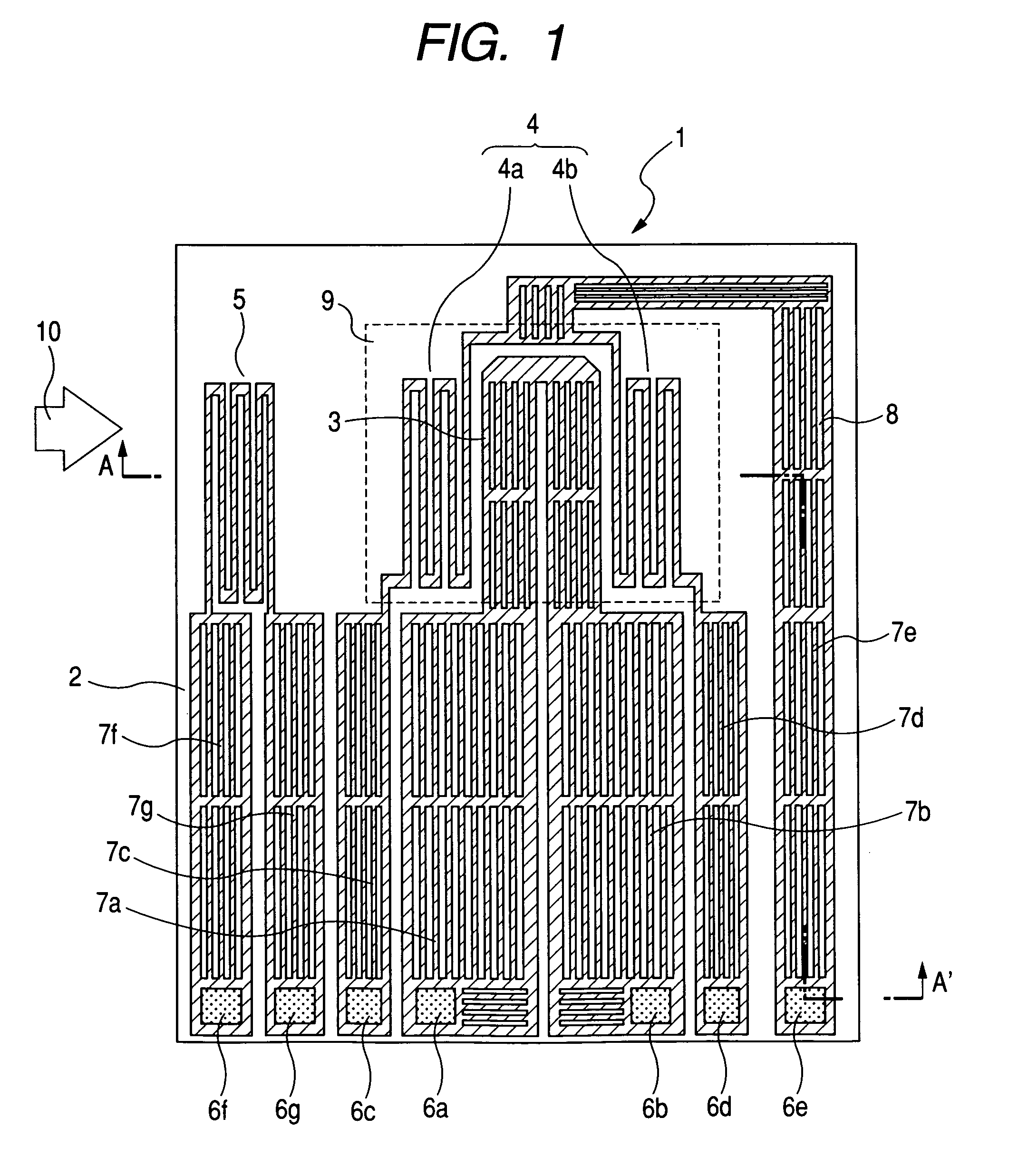
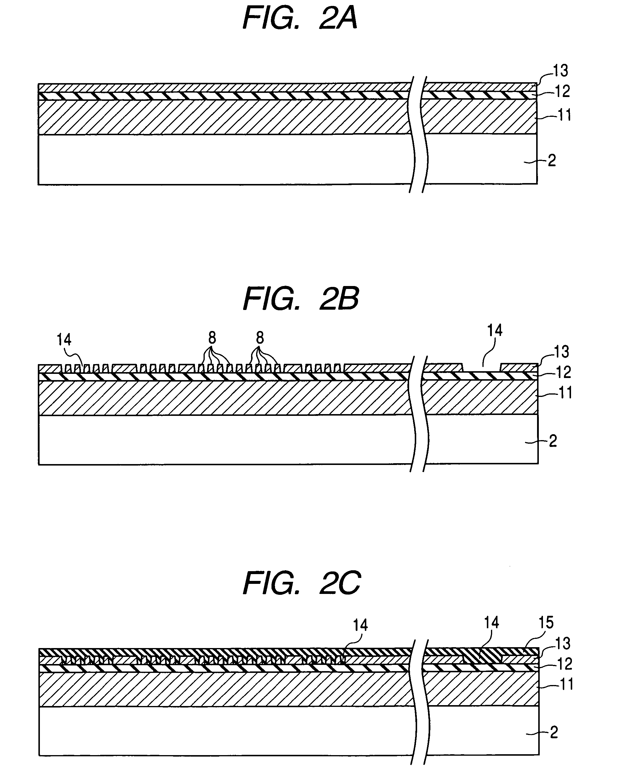
[0029]FIG. 1 is a plan view showing a flow sensor with metal film resistor according to the first embodiment of the present invention. FIGS. 2A through 2G are sectional views taken along the line A-A′ in FIG. 1 so as to illustrate processes of fabricating the flow sensor with metal film resistor.

[0030]FIG. 1 is a plan view showing an example of the flow sensor according to the first embodiment.

[0031]The flow sensor with metal film resistor is provided as a measurement element 1 that includes a semiconductor substrate 2, a resistance heat detector 3, a resistance temperature detector 4, an air resistance temperature detector 5, terminal electrodes 6a through 6g, and leading wires 7a through 7g. The semiconductor substrate 2 is made of single-crystalline silicon. The resistance heat detector 3 is formed on the semiconductor substrate 2 via the intermediation of an insulating film. The resistance temperature detector 4 detects the temperature of air heated by the resistance heat detect...

second embodiment

[0051]The second embodiment of the present invention uses a double-layered structure of an adhesion layer and a metal film for the resistance heat detector, the air resistance temperature detector, the upstream resistance temperature detector, the downstream resistance temperature detector, and the leading wire included in the measurement element as the flow sensor with metal film resistor. The topmost layer is provided with a protective film.

[0052]FIG. 7 diagrams an example of the flow sensor with metal film resistor according to the second embodiment and shows a fragmentary sectional view correspond to the line A-A′ in FIG. 1 according to the first embodiment. A first insulating film 47 is formed on a semiconductor substrate 46 made of single-crystalline silicon. Further, a second insulating film 48 and a third insulating film 49 are formed in order. For example, the first insulating film 47 is a SiO2 film approximately 200 nm thick formed in a high-temperature furnace body. The s...

third embodiment

[0059]FIG. 8 is a plan view showing a main part of an example of the flow sensor with metal film resistor according to the third embodiment of the invention.

[0060]A measurement element 101 as the flow sensor with metal film resistor includes the following. A semiconductor substrate 102 is made of single-crystalline silicon. A resistance heat detector 103 is formed on the semiconductor substrate 102 via an insulating film. A resistance temperature detector for resistance heat detector 104 detects the temperature of the resistance heat detector 103. A resistance temperature detector 105 detects the temperature of air heated by the resistance heat detector 103 and includes two upstream resistance temperature detectors 105a and 105b and two downstream resistance temperature detectors 105c and 105d. An air resistance temperature detector 106 measures the air temperature. There are provided heater temperature control resistors 107 and 108. Electrodes 109a through 109i connect a signal fro...


PUM


Abstract

There is a need for providing a flow sensor with metal film resistor that improves detection sensitivity using a metal film for a resistance heat detector and a resistance temperature detector. The flow sensor with metal film resistor is structured to form a resistance heat detector, a resistance temperature detector for resistance heat detector for measuring temperature of the resistance heat detector, an upstream resistance temperature detector, a downstream resistance temperature detector, and an air resistance temperature detector on a silicon substrate. Plural floating-island insulators are provided for the resistance heat detector and within wiring thereof.

Description

CLAIM OF PRIORITY[0001]The present application claims priority from Japanese Patent Application JP 2008-017015 filed on Jan. 29, 2008, the content of which is hereby incorporated by reference into this application.FIELD OF THE INVENTION[0002]The present invention relates to a flow sensor with metal film resistor and more particularly to a flow sensor with metal film resistor appropriate to a thermal air flow meter for measuring air flow taken into an internal combustion engine.BACKGROUND OF THE INVENTION[0003]A flow sensor with metal film resistor is provided for an electrically controlled fuel injection system of an internal combustion engine of an automobile and the like and is used for an air flow meter that measures the intake air flow. Presently, the thermal type air flow sensor with metal film resistor goes mainstream because it can directly detect the mass air volume.[0004]In particular, constant attention has been focused on a thermal airflow sensor fabricated by the semicon...

Claims


Application Information

Patent Timeline
Patent Type & Authority Patents(United States)
IPC IPC(8): G01F1/68G01C19/00G01F1/692
CPCG01F1/688G01F1/6845
Inventor SAKUMA, NORIYUKI
Owner HITACHI LTD
Why Eureka
Try Eureka