
Assertion generating system, program thereof, circuit verifying system, and assertion generating method

a technology of assertion generation and assertion generation, applied in the direction of instrumentation, program control, cad circuit design, etc., can solve the problems of insufficient circuit verification or test scenario that can extract bugs, increase circuit size, and inability to form, so as to achieve high reliability and high efficiency in assertion verification

Active Publication Date: 2009-10-13
SEMICON DESIGN TECH LLC
View PDF11 Cites 23 Cited by
  • Summary
  • Abstract
  • Description
  • Claims
  • Application Information

AI Technical Summary

Benefits of technology

[0054]The object of the present invention is to solve the problems in the conventional technologies, for example, to enable high reliability and high efficiency in assertion verification for an LSI and so on.
[0060]According to the present invention, since the assertion description of a property to be verified is automatically generated from electronic data of the state transition figure which is attached to the specifications, matching the circuit specification with the assertion is established. Therefore, work to be used for debugging the assertion can be reduced. In addition, since the generated assertion is a function coverage point generated by comprehensive search of paths of the state transition, after the verification, feedback that a path has not been tested can be obtained by a function coverage report; consequently, missing a test of a corner case can be prevented. In addition, since the assertion description of a property to be verified is automatically generated from electronic data of a selection condition of timing charts and signals which are attached to the specifications, or electronic data of figures or a table form in which a process sequence is noted or defined, matching the circuit specification with the assertion is established. Therefore, work to be used for debugging the assertion can be reduced. In many cases, the selection condition of timing charts and signals which are attached to the specifications or the process sequence is an important assertion to be surely tested at the time of verification; however, since the assertion generated in the embodiment is an important property, a designer who does not know the specifications and the circuit functions sufficiently can execute verification by using the property. As a result, the number of times of revising the system caused by missing verification can be reduced.

Problems solved by technology

Recently, a system has been revised or a revised edition of a system has been published frequently, caused by missing verification of a corner case due to the complexity of a circuit and an increase of circuit size of a semiconductor integrated circuit, by missing confirmation of interface specifications among blocks allocated to plural designers due to group work, or by specification errors of a reusable core purchased from a third party.
These problems come from, for example, insufficient circuit verification or a test scenario that can extract bugs, which were not able to be formed because a corner case and core specifications of the third party were not understood sufficiently.
However, in such an assertion verifying technology, for example, in a case where the assertion description language is written by a manual input when the specifications are defined, there is a possibility that a mistake may be made in the assertion itself.
As a result, a report of the warning of the assertion violation and the function coverage obtained by the assertion verification cannot be fed back to prevent the system revision and the revised edition of the system.
Consequently, the verification efficiency becomes worse.
In other words, the major premise of the assertion verifying technology is that the circuit specifications and the assertion description match each other; however, there is no method to confirm the matching before executing the simulation.
Further, with respect to a complex finite state machine, it is difficult to describe a sequence of a comprehensive state transition by manual operation.
Consequently, mixing a mistake in an object to be matched, that is, in the model of the state transition machine which should be the circuit specifications, cannot be avoided.
However, in this technology, since the assertion which is the circuit specifications is extracted from the design data, matching the circuit specifications with the assertion description cannot be assured.
Consequently, in the conventional technologies, matching the circuit specifications with the assertion description cannot be assured.

Method used


Image

  • Assertion generating system, program thereof, circuit verifying system, and assertion generating method
  • Assertion generating system, program thereof, circuit verifying system, and assertion generating method
  • Assertion generating system, program thereof, circuit verifying system, and assertion generating method

Examples


Embodiment Construction

[0077]Next, referring to the drawings, embodiments of the present invention are explained in detail.

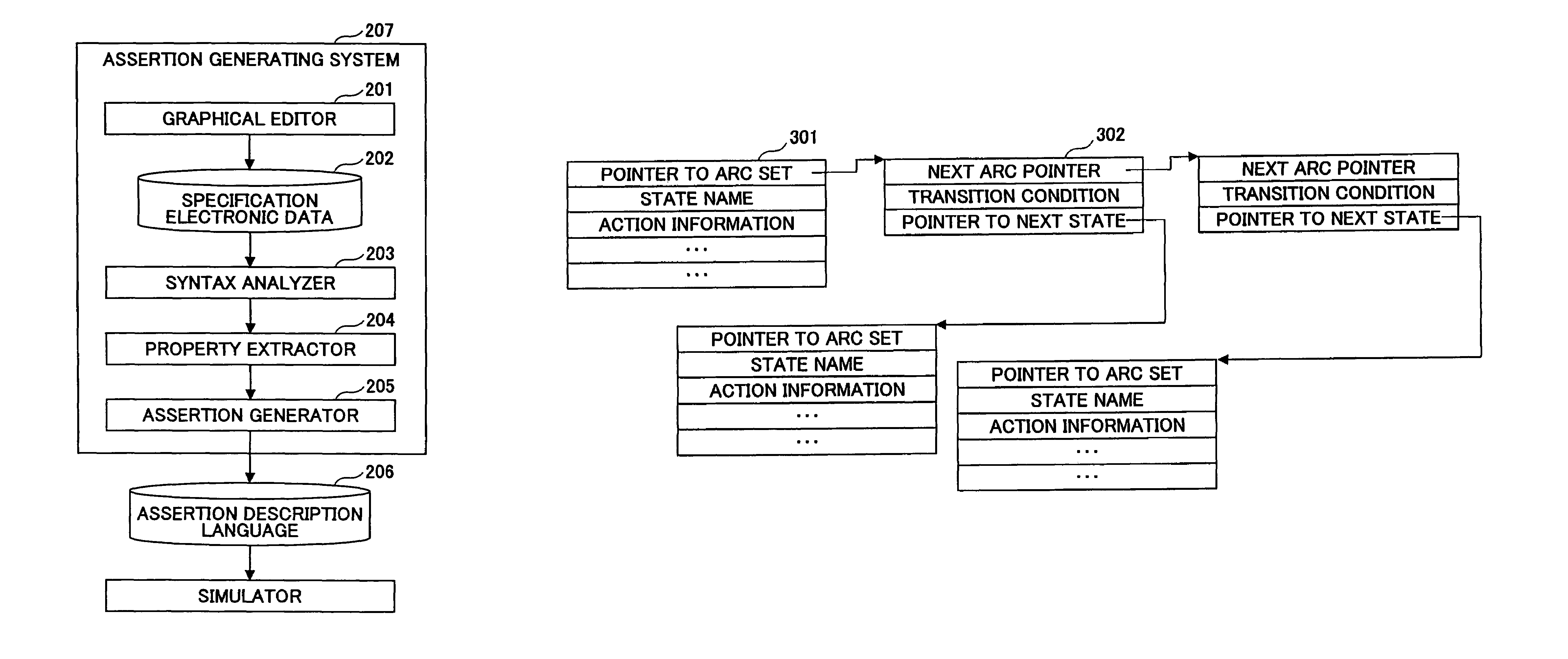
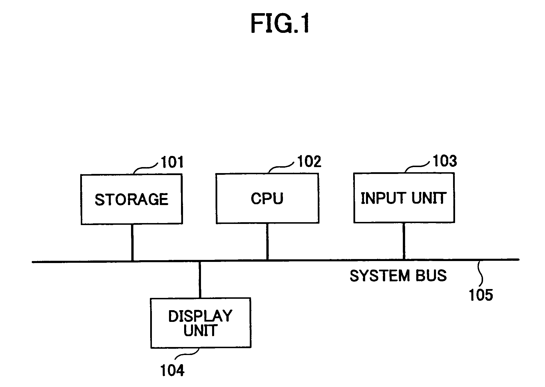
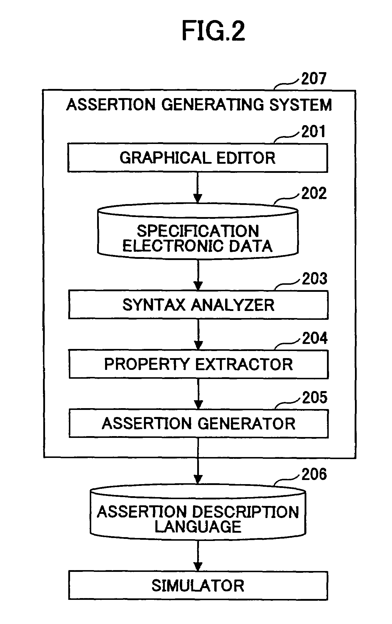
[0078]FIG. 1 is a block diagram showing a structural example of hardware of which an assertion generating system and a circuit verifying system according to the present invention consist. FIG. 2 is a block diagram showing a first functional structure example of the assertion generating system and the circuit verifying system using the assertion generating system according to the present invention. FIG. 3 is a diagram showing a memory content example of a graphic structure using in the assertion generating system according to the present invention. FIG. 4 is a diagram showing a state transition figure and a graphic structure using in the assertion generating system according to the present invention. FIG. 5 is a block diagram showing a second functional structure example of the assertion generating system according to the present invention. FIG. 6 is a block diagram showing a third fun...


PUM


Abstract

An assertion generating system is disclosed. In an assertion generating system 207, a graphical editor 201 generates design data of a semiconductor integrated circuit by graphically editing a specification (finite state machine, process sequence) of the semiconductor integrated circuit with the use of a state transition table and a state transition figure or by editing the process sequence into a timing chart and a time series figure based on user operations, and a syntax analyzer 203 and a property extractor 204 generate a property that verifies the specification of the semiconductor integrated circuit based on the design data. The assertion generator 205 converts the property into an assertion description language 206.

Description

TECHNICAL FIELD[0001]The present invention relates to a technology that executes circuit verification of an LSI (large scale integration) and so on using a process based on a computer program, and a verifying technology for verifying so that design violation and missing verification do not exist in design data by converting a property of a circuit to be verified into an assertion description and inputting the assertion description to a simulator when the design data of a circuit in a RTL (register transfer level) are dynamically verified by the simulator; and in particular, an assertion generating system, a program thereof, a circuit verifying system, and an assertion generating method, in which the above technology is used.[0002]The property to be discussed below is plain text that defines operations intended and expected in design data to be verified. For example, the property defines a relation between reception and response of a request signal and an approval signal in an arbite...

Claims


Application Information

Patent Timeline
Patent Type & Authority Patents(United States)
IPC IPC(8): G06F17/50
CPCG06F17/5022G06F30/33
Inventor YAMADA, TAKAMITSU
Owner SEMICON DESIGN TECH LLC
Learn More