Titanium alloy valve lifter

a technology of titanium alloy and valve lifter, which is applied in the direction of valve arrangement, machines/engines, mechanical equipment, etc., can solve the problems of brittle -case, poor sliding properties of the cam, and more likely to occur pitting, etc., and achieves moderate grinding energy of the vibration barrel machine, good surface roughness, and high grinding energy

Inactive Publication Date: 2009-10-13
HONDA MOTOR CO LTD
View PDF7 Cites 0 Cited by
  • Summary
  • Abstract
  • Description
  • Claims
  • Application Information

AI Technical Summary

Benefits of technology

[0010]When the thickness of the α-case is less than 3 μm, the sliding properties on the cam are inadequate. When the thickness of the α-case is more than 15 μm, the α-case is brittle, and pitting is more likely to occur. Further, if the oxygen diffusion layer with a thickness of at least 10 μm were not provided under the α-case, cracks would be more likely to occur in the α-case because the hardness of the α-case is too different from that of the texture thereunder. Cracks that are formed in the α-case increase the likelihood of causing wear and pitting. Moreover, fatigue failures start from such cracks, and the strength is reduced.
[0012]By setting the thickness of the α-case not less than 5 μm and not more than 10 μm, the valve lifter provides adequate capabilities even under severe conditions which cannot occur in normal driving conditions.
[0016]This alloy is given an increased strength by containing pure titanium as a basic material and increased amounts of Fe and O added as impurities. Accordingly, the alloy is excellent in cold or warm plastic workability despite the high strength thereof, thus facilitating shaping the valve lifter by forging. Furthermore, this alloy does not include an element improving oxidation resistance such as aluminum (Al) in the composition. For this reason, the α-case can be formed in a thicker layer than the layers that can be formed in the case of conventional alloys such as Ti-6Al-4V, and therefore this alloy is preferred to ensure proper wear resistance of the sliding surface on which the cam slides. When the contents of Fe and O are less than 0.6 wt % and 0.24 wt %, respectively, the strength required for the valve lifter cannot be obtained. When the contents of Fe and O exceed 1.4 wt % and 0.44 wt %, respectively, deformation resistance is increased, and forgeability is significantly reduced, so that cracks are produced and the life of the mold is reduced significantly, thus impairing mass productivity.
[0020]Grinding energy of the vibration barrel machine is moderate, and grinding by the vibration barrel machine can remove the oxide layer without damaging the α-case and oxygen diffusion layer under the oxide layer. For example, the oxide layer could be removed by shot blasting or the like. However, the grinding energy is high in the case of the shot blasting. Consequently, when comparison is made between a part where the removal of the oxide layer has been completed and another part where the removal of the oxide layer has not yet fully completed, it is observed that the α-case is roughed in the part where the removal of the oxide layer has been completed, and good surface roughness cannot be obtained on the layer of the α-case. On the contrary, by grinding with the use of the vibration barrel machine, the operation of separating and removing the oxide layer on the surface of the valve lifter can be performed in a comparatively simplified removal step. Moreover, the vibration barrel machine can simultaneously grind a number of valve lifters together to remove the oxide layer, thus increasing an efficiency of the step to separate and remove the oxide layer on the surface of the valve lifter and reducing the cost for the operation. Moreover, grinding with the use of the vibration barrel machine allows removal of the oxide layer and simultaneously allows surface polishing, and it is therefore possible to provide good surface roughness.

Problems solved by technology

When the thickness of the α-case is less than 3 μm, the sliding properties on the cam are inadequate.
When the thickness of the α-case is more than 15 μm, the α-case is brittle, and pitting is more likely to occur.
Further, if the oxygen diffusion layer with a thickness of at least 10 μm were not provided under the α-case, cracks would be more likely to occur in the α-case because the hardness of the α-case is too different from that of the texture thereunder.
Cracks that are formed in the α-case increase the likelihood of causing wear and pitting.
Moreover, fatigue failures start from such cracks, and the strength is reduced.

Method used


Image

  • Titanium alloy valve lifter
  • Titanium alloy valve lifter
  • Titanium alloy valve lifter

Examples


example 1

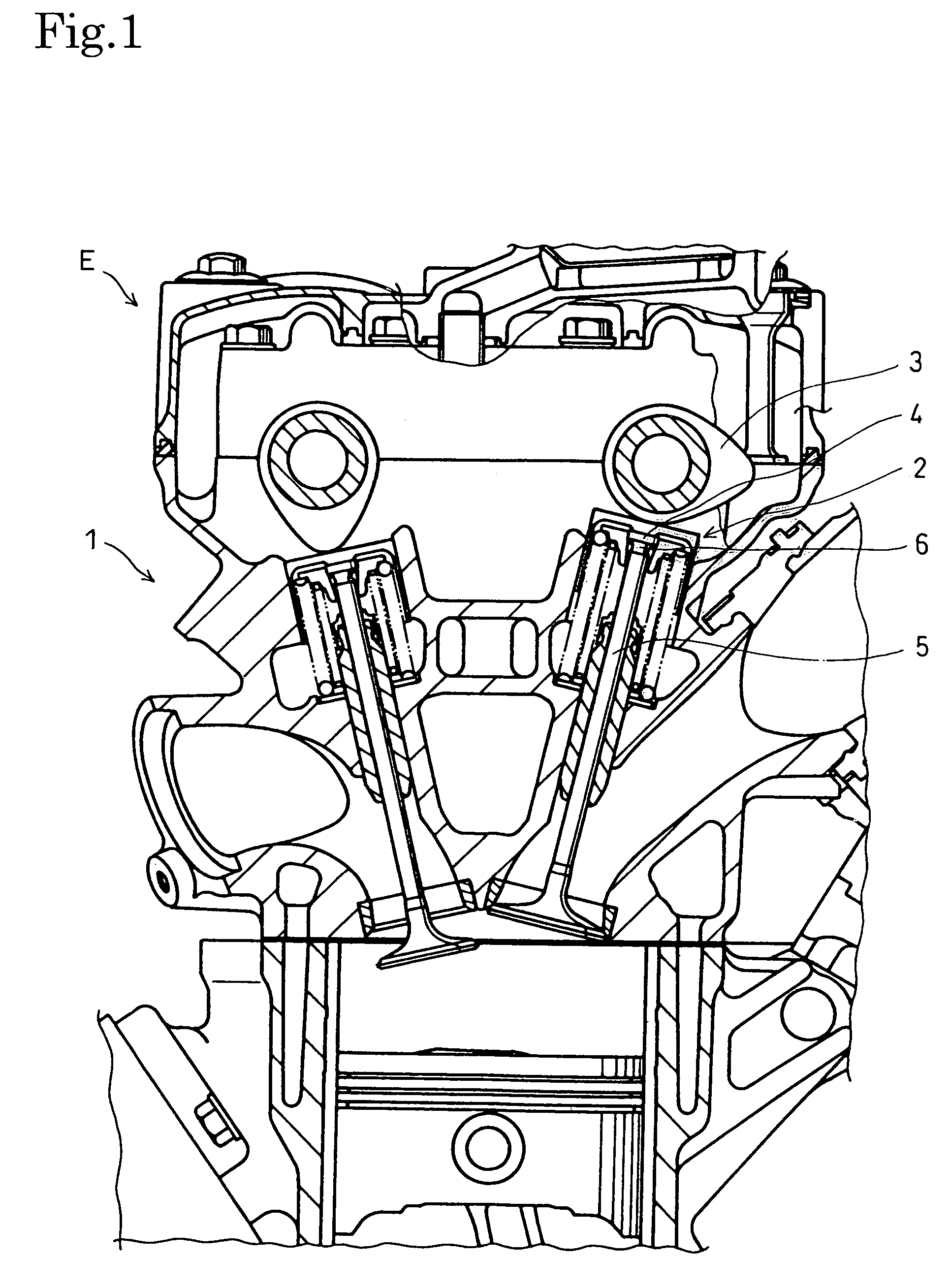
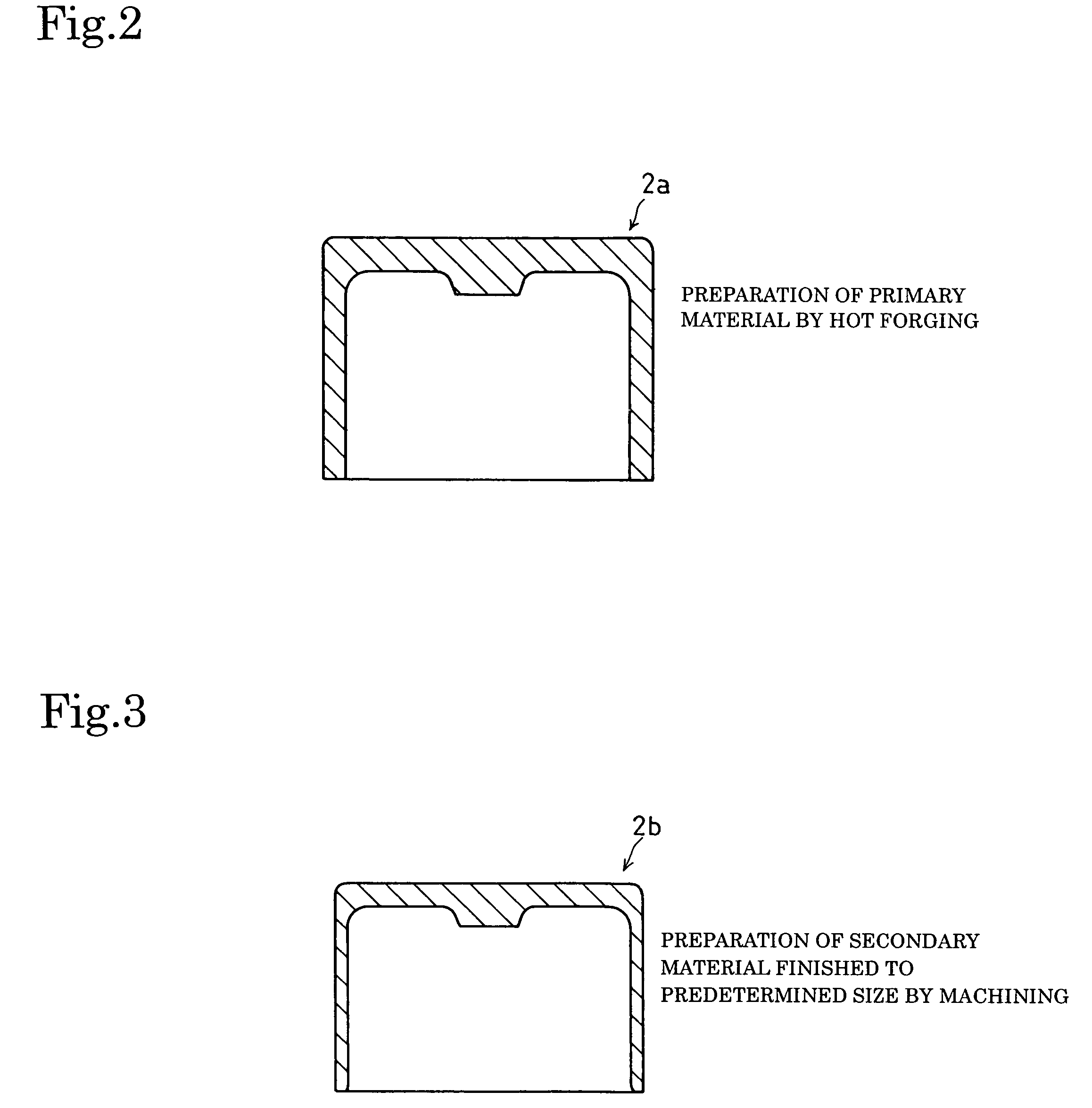
[0029]Using a titanium alloy composed of 0.96 wt % of iron (Fe), 0.32 wt % of oxygen (O), and the remainder including titanium (Ti) and unavoidable impurities, billets (diameter=28 mm and height=7 mm) were produced by machining. Lubricant was then applied to these billets and the billets were dried sufficiently. These billets were forged by a press with a die set, to obtain primary materials 2a for the valve lifter 2. FIG. 2 shows such a primary material 2a.

[0030]Parts of each of the primary materials 2a were cut by machining and ground to produce a secondary material 2b as shown in FIG. 3. At this time, dimensions of the parts were nearly equal to those of a finished valve lifter.

[0031]After being washed sufficiently, the secondary materials 2b were put into a heating furnace at 700° C. and held for seven hours for an oxidation treatment. The atmosphere in the furnace was atmospheric air. As a result, as shown in FIG. 5, (1) an oxide layer 21, (2) an α-case 22, and (3) an oxygen d...

example 2

[0037]In order to ascertain a proper thickness of the α-case 22, the valve lifters 2 whose α-cases 22 were about 2, 3, 5, 7, 10, 15, and 18 μm thick were produced by adjusting the temperature and time period of the oxidation treatment in a similar process to that of the Example 1, and the valve lifters 2 were subjected to the same durability tests in a similar way. The surface roughnesses thereof were set to uniform maximum height roughness Rz of 3 (JIS B 0601:2001). In the valve lifter 2 whose α-case 22 was 2 μm thick, the oxygen diffusion layer 23 under the α-case 22 was about 7 μm thick. In the valve lifters 2 whose α-case 22 was 3 μm thick or more, the oxygen diffusion layer 23 was 10 μm thick or more. The results of the durability tests show that in the case of the valve lifter 2 whose α-case 22 and oxygen diffusion layer 23 were 2 μm and 7 μm thick, respectively, wear occurred on the sliding surface on which the cam 3 slides during the durability tests. Therefore, the durabili...

example 3

[0039]Next, using the valve lifters 2 in which the α-case 22 was about 7 μm thick and the oxygen diffusion layer 23 was about 20 μm thick, effects of the roughness of the sliding surface on which the cam 3 slides were checked with the roughness varied. The valve lifters 2 with maximum height roughnesses Rz of about 2, 3, 4, 5, and 7 were prepared by grinding with the use of the vibration barrel machine to obtain the valve lifters 2 having surface roughness of a maximum height roughness Rz of about 2 and by subsequenly adjusting the roughnesses to the above values by means of minute-particle shot blasting. Each of these valve lifters 2 was set in the aforementioned internal combustion engine for the durability tests. After the tests were finished, the amount of wear of the cam 3 was measured. In the cam 3 which was caused to slide on each of the valve lifters 2 with a maximum height roughness Rz of not more than 4, the amount of wear was equal to or less than that in the cam 3 which ...


PUM

PropertyMeasurementUnit
thicknessaaaaaaaaaa
thicknessaaaaaaaaaa
thicknessaaaaaaaaaa

Abstract

A lightweight and high-strength valve lifter is excellent in wear resistance and sliding properties. The valve lifter is made of a titanium alloy having a hardened layer on the top surface thereof, on which a cam is caused to slide. The hardened layer is composed of an α-case and an oxygen diffusion layer under the α-case. The α-case 22 is formed in a thickness of not less than 3 μm and not more than 15 μm. The oxygen diffusion layer has a thickness of not less than 10 μm. The hardened layer on the top surface of the valve lifter is formed by oxidation treatment in a furnace at a temperature of not less than 600° C. An outermost oxide layer 21 formed on the α-case as a result of the oxidation treatment is removed.

Description

BACKGROUND OF THE INVENTION[0001]1. Field of the Invention[0002]The present invention relates to a valve lifter made of titanium alloy and a method of manufacturing the same.[0003]2. Description of the Related Art[0004]A valve lifter in a valve operating mechanism of an internal combustion engine for racing is generally made of titanium. In car races there are few demands in terms of cost, and therefore the valve lifter is subjected to a surface treatment such as expensive ion plating in order to improve wear resistance. On the other hand, as for applying the titanium valve lifter to mass-produced vehicles, there are no practical cases of using a surface-treated titanium alloy especially due to the problem of costs because titanium itself is expensive and requires an expensive surface treatment. In addition, the valve lifter for mass-produced vehicles requires better properties in terms of the wear resistance than that for racing vehicles. A known example of the valve lifter made of...

Claims


Application Information

Patent Timeline
Patent Type & Authority Patents(United States)
IPC IPC(8): F01L1/14
CPCF01L1/053F01L1/16F01L1/143
Inventor HORIMURA, HIROYUKIDOI, KOSUKETAKATA, MASAYA
Owner HONDA MOTOR CO LTD
Why Eureka
Try Eureka