
Governor and a power generating device and an apparatus using the governor

a power generating device and governor technology, applied in the direction of instruments, horology, etc., can solve the problems of not being able to hear the correct time, not being able being unable to control the power supply, etc., to achieve low cost, no effect of affecting the power supply, and reducing the cos

Active Publication Date: 2009-09-15
SEIKO EPSON CORP
View PDF17 Cites 6 Cited by
  • Summary
  • Abstract
  • Description
  • Claims
  • Application Information

AI Technical Summary

Benefits of technology

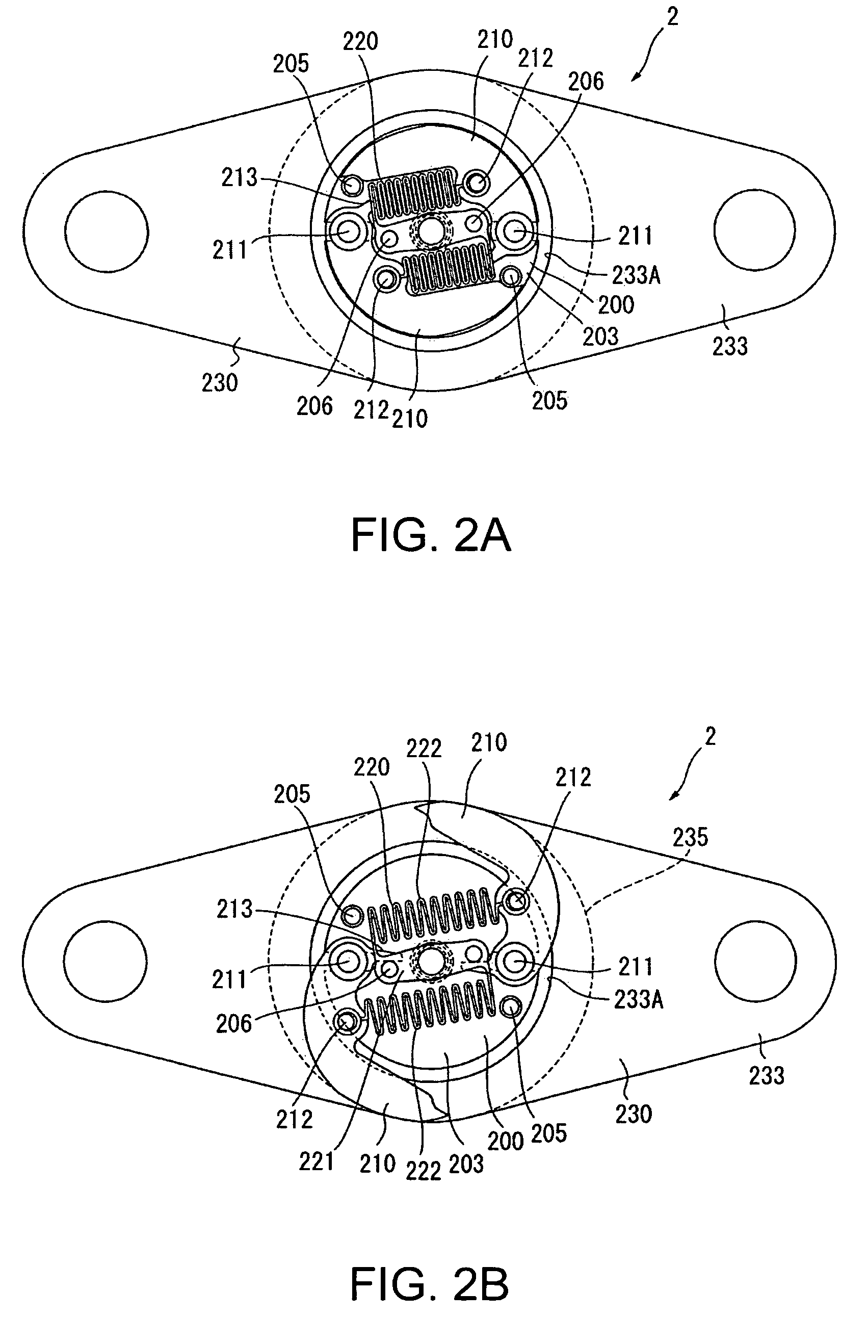
[0127]The present invention therefore provides a governor, and a power generating device and apparatus using the governor, that can be rendered compactly in a small space, can be used in devices that are driven with little power, do not produce wear particles or noise, are low cost, are not affected by differences in attitude, are not affected by magnetism, and afford excellent durability.

Problems solved by technology

This type of electronically controlled governor requires a generator having a stator, coil, and rotor, and is therefore relatively large and relatively expensive.
The repeater or sonnerie indicates the time by the number of times the gong is struck, and the user may not be able to distinguish the strikes if the gong is struck too quickly, may miscount the strikes if the gong is struck too slowly, and may therefore not hear the correct time.
The reason that a governor consisting of a balance, hairspring, pallet fork, and escape wheel for a timepiece is not used as the governor in a repeater or sonnerie mechanism is that the escapement and governor is large in size (particularly the horizontal size) and therefore not space efficient, costly, and requires so much energy to drive the hammer that a spring with low torque cannot be used.
More particularly, if the speed of the balance is increased approximately 100 times, a short hairspring must be used, wear on the shaft and striking portions is severe, and using such a governor is therefore not practical.

Method used


Image

  • Governor and a power generating device and an apparatus using the governor
  • Governor and a power generating device and an apparatus using the governor
  • Governor and a power generating device and an apparatus using the governor

Examples


first embodiment

[0153]A first embodiment of the present invention is described next.

[0154]FIG. 1 is a plan view of a timepiece 1, with a display showing time information, according to this first embodiment of the invention. The timepiece 1 has a sonnerie mechanism (operating unit) 3 rendered on the dial side of the base timepiece, and the governor 2 according to the invention is used to operate the sonnerie mechanism.

[0155]The movement for driving the hands of the timepiece 1 could be a movement for a mechanical timepiece, an analog quartz timepiece, or an electronically controlled mechanical timepiece. The sound of the sonnerie mechanism is made difficult to hear by the ticking sound produced by the governor having a balance, hairspring, pallet fork, and escape wheel in a mechanical timepiece, however, and by the sound of magnetostriction and gear teeth striking in an analog quartz timepiece. An electronically controlled mechanical timepiece, which produces less noise, is therefore preferably used...

second embodiment

[0265]A second embodiment of the invention is described next with reference to FIG. 9A to FIG. 9C. This second embodiment differs from the governor 2 of the first embodiment by slightly modifying the shape of the outside edge of the wings 210. Other aspects of this embodiment are the same as in the first embodiment, and further description thereof is thus omitted.

[0266]More specifically, the wings 210A in this second embodiment of the invention match the shape of the inside circumference edge of the opening 233A in the opposing plates 233. That is, part of the outside edge of the wing 210A, and even more specifically the profile of the edge from the distal end of the wing 210A to near the wing pin 211, conforms to the shape of the inside edge of the opening 233A in the opposing plates 233.

[0267]The governor 2 according to this embodiment of the invention affords the same effects as the first embodiment.

[0268]In addition, the area of the wings 210A inserted between the opposing plate...

third embodiment

[0269]As shown in FIG. 10 and FIG. 11, the opposing member 300 in this third embodiment of the invention renders the pair of opposing plates 233 above and below the governor 2 in unison. The opposing member 300 therefore has a channel 301 that the wings 210 enter when centrifugal force drives the wings 210 to the outside.

[0270]This embodiment of the invention assembles two opposing members 300 each having a C-shaped channel 301 to render a single annular channel 301.

[0271]The opposing members 300 can move linearly guided by guide pins 302 inserted to oblong holes rendered in the opposing members 300. A spring 303 formed in unison with each opposing member 300 urges the opposing members 300 apart, that is, away from the rotational axis of the rotor 200.

[0272]The opposing members 300 are disposed so that the gap between the opposing members 300 can be minutely adjusted using adjustment screws 304 screwed into the plate 5. More specifically, if the adjustment screws 304 are screwed in ...


PUM


Abstract

It is intended to provide a governor that is small, does not produce wear particles or noise, is low cost, is not affected by differences in attitude, is not affected by magnetism, and has outstanding durability. The governor has a rotor that rotates using energy supplied from an energy storage means through a power transfer means, a wing having wing surfaces perpendicular to the rotational axis of the rotor, and disposed movably to an outside circumference side radially to the rotor by means of centrifugal force produced by rotor rotation, a zigzag spring disposed between the rotor and wing for pulling the wing to the inside circumference side radially to the rotor, and an opposing member disposed to the outside circumference of the rotor and having an opposing surface located opposite and separated a predetermined gap from the wing surface when the wing moves to the outside circumference side radially to the rotor.

Description

CROSS REFERENCE TO RELATED APPLICATION[0001]This application claims priority to Japanese Patent Application Nos. 2005-293875, 2006-178251, and 2006-189813. The entire disclosure of Japanese Patent Application Nos. 2005-293875, 2006-178251, and 2006-189813 is hereby incorporated herein by reference.BACKGROUND OF THE INVENTION[0002]1. Field of Technology[0003]The present invention relates to a governor that uses the viscosity of a fluid, and relates to a power generating device and to an apparatus that use the governor.[0004]2. Description of Related Art[0005]In order to keep an apparatus that uses an energy storage means, which stores, for example, the mechanical energy of a spring, the potential energy of a counterweight, or the thermal energy of heat accumulated in or extracted from a sealed bellows type container, as the drive power source operating at a constant speed, a governor is used to gradually release the stored energy.[0006]The governor may be a mechanical governor or an ...

Claims


Application Information

Patent Timeline
Patent Type & Authority Patents(United States)
IPC IPC(8): G04B21/02G01F1/06G04B25/00H02K7/10
CPCG05D13/18G04B17/30G04B21/06
Inventor MOTEKI, MASATOSHITAKAHASHI, OSAMU
Owner SEIKO EPSON CORP
Learn More