
Surface acoustic wave device

a surface acoustic wave and waveguide technology, applied in piezoelectric/electrostrictive/magnetostrictive devices, piezoelectric/electrostriction/magnetostriction machines, electrical equipment, etc., can solve the problem of practically large frequency fluctuation amount, achieve high q value, reduce size, and efficiently use the reflection of saws

Active Publication Date: 2009-09-15
SEIKO EPSON CORP
View PDF29 Cites 26 Cited by
  • Summary
  • Abstract
  • Description
  • Claims
  • Application Information

AI Technical Summary

Benefits of technology

The technical effect of this patent is to address the problem of large frequency fluctuations in ST cut quartz substrates used as a piezoelectric substrate in SAW devices. The patent proposes a solution to reduce the size of the device while maintaining its performance.

Problems solved by technology

A problem to be solved is that, when an ST cut quartz substrate is used as a piezoelectric substrate, the secondary temperature coefficient of a frequency-temperature characteristic is large as −0.034 (ppm / ° C.2) so that a frequency fluctuation amount becomes considerably large practically.

Method used


Image

  • Surface acoustic wave device
  • Surface acoustic wave device
  • Surface acoustic wave device

Examples


Embodiment Construction

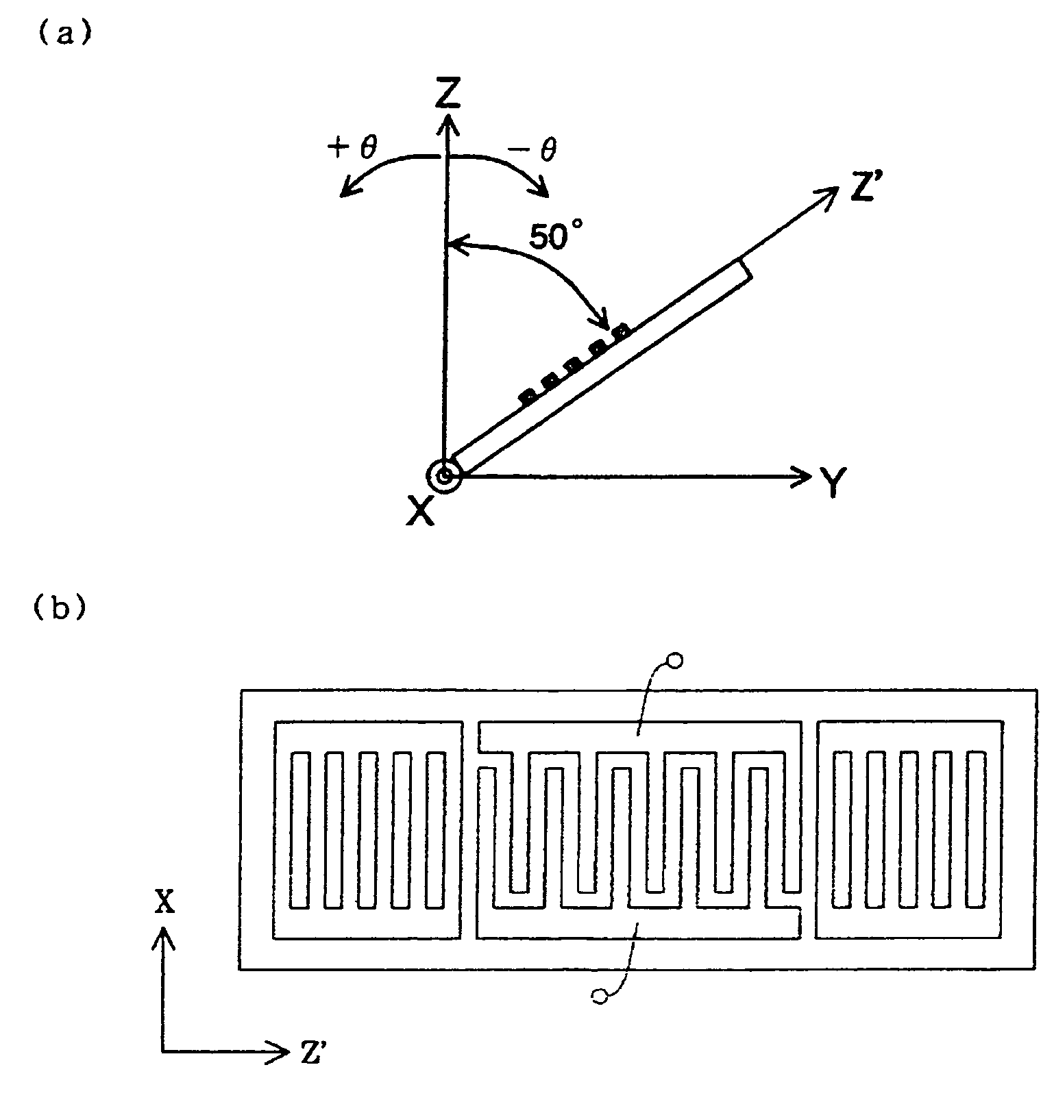
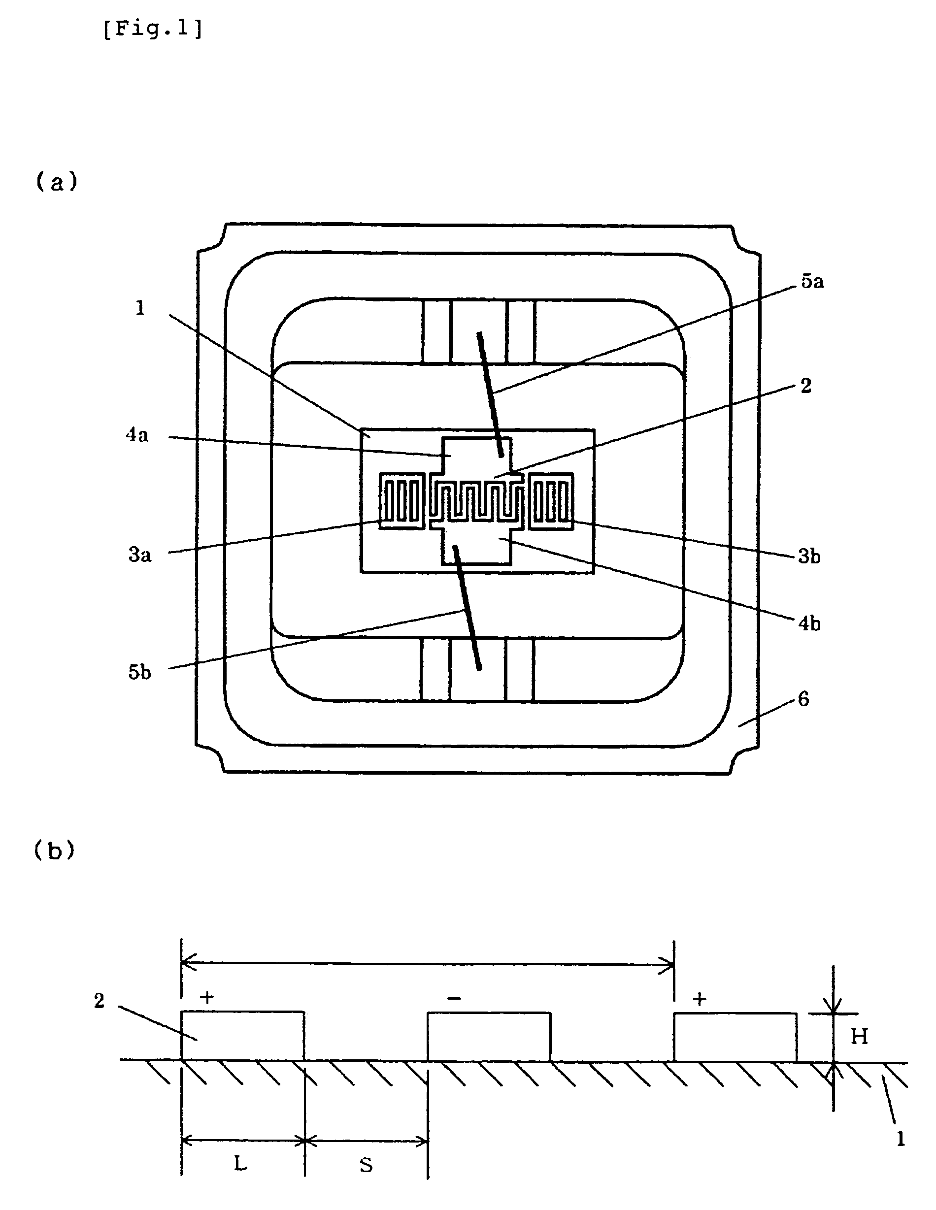
[0029]The present invention will be explained below in detail based on embodiments shown in the drawings. FIG. 1(a) is a plan view of a SAW resonator according to the present invention, where an IDT 2 having positive electrode fingers and negative electrode fingers mutually inserted and grating reflectors 3a and 3b for reflecting a SAW positioned on both sides of the IDT 2 are arranged on a piezoelectric substrate 1. Input / output pads 4a and 4b of the IDT 2 and input / output terminals of a package 6 are electrically connected to each other by metal wires 5a and 5b and an opening portion of the package 6 is sealed by a lid air-tightly. As shown in FIG. 14, the piezoelectric substrate 1 is a quartz flat plate where a cut angle θ of a rotation Y cut quartz substrate is set near a position rotated from a crystal Z-axis in a counterclockwise direction by an angle of −50°, and a propagation direction of a SAW is set to a approximately perpendicular direction (90°±5°) to a crystal X-axis, a...


PUM


Abstract

An object of the invention is to provide a SAW device where a device size is made smaller than that of a conventional structure, has a high Q value, and is excellent in a frequency temperature characteristic in a SAW device using a quartz substrate. Therefore, IDTs 2 including pluralities of electrode fingers mutually inserted and grating reflectors 3a and 3b positioned on both sides of the IDTs 2 are disposed on a piezoelectric substrate 1. The piezoelectric substrate 1 is a quartz flat plate where a cut angle θ of a rotation Y cut quartz substrate is set to satisfy a range of −64.0°<θ<−49.3° in a counterclockwise direction from a crystal Z-axis and a propagation direction of a surface acoustic wave is set to 90°±5° to a crystal X-axis, and a surface acoustic wave to be excited is an SH wave. The IDTs 2 and the grating reflectors 3a and 3b are made from Al or alloy including Al as a main component, and when a wavelength of a surface acoustic wave is represented as λ, an electrode film thickness H / λ standardized by the wavelength is set to satisfy 0.04<H / λ<0.12.

Description

TECHNICAL FIELD[0001]The present invention relates to a surface acoustic wave device using a quartz substrate in which a device size is reduced, a Q value is increased, and a frequency-temperature characteristic is improved.BACKGROUND ART[0002]In recent years, a surface acoustic wave (hereinafter, SAW) device is widely utilized as apart for a terminal for mobile communication, a vehicle-mounted equipment, or the like, and it is strongly demanded to be downsized, have a high Q value, and be excellent in frequency stability.[0003]As a SAW device realizing these demands, there is a SAW device using an ST cut quartz substrate. The ST cut quartz substrate is a cut name of a quartz plate having a plane (XZ′ plane) obtained by rotating an XZ plane from a crystal Z-axis in a counterclockwise direction by an angle of 42.75° utilizing a crystal X-axis as a rotation axis, and it utilizes a SAW (hereinafter, called ST cut quartz SAW) that is a (P+SV) wave propagated in a crystal X direction, ca...

Claims


Application Information

Patent Timeline
Patent Type & Authority Patents(United States)
IPC IPC(8): H03H9/125H03H9/25H03H3/10H03H9/02H03H9/145H03H9/64
CPCH03H9/02551H03H9/145H03H9/64H03H9/02H03H9/25
Inventor MORITA, TAKAOOHWAKI, TAKUYA
Owner SEIKO EPSON CORP
Learn More