Mass spectrometric system and mass spectrometry
a mass spectrometry and mass spectrometry technology, applied in the field of mass spectrometry system and analysis method, can solve the problems of complicated operation and complicated operation, and achieve the effect of high accuracy and efficient sample separation
- Summary
- Abstract
- Description
- Claims
- Application Information
AI Technical Summary
Benefits of technology
Problems solved by technology
Method used
Image


Examples
first embodiment
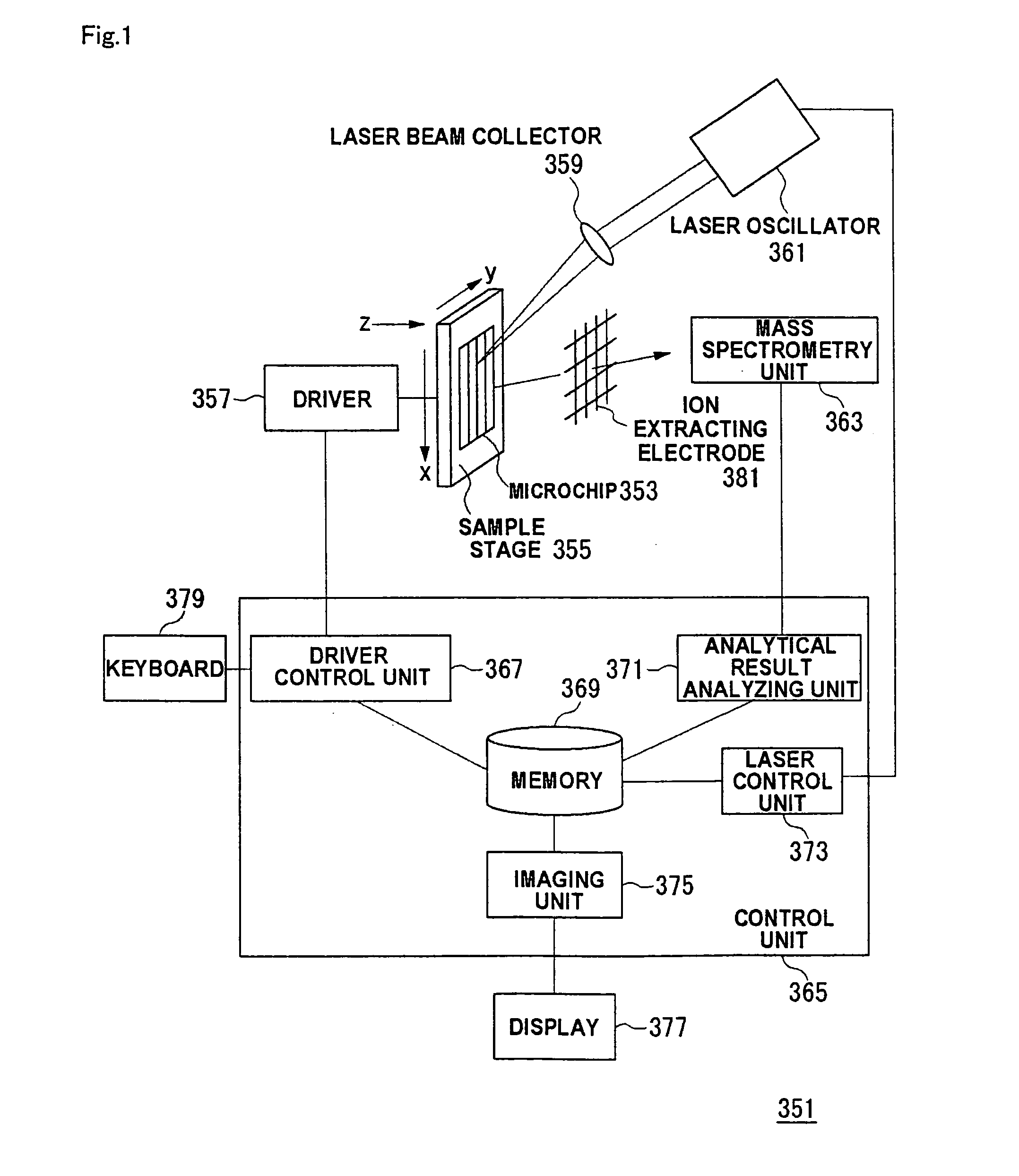
[0161]FIG. 1 is a view showing a configuration of a mass spectrometry system according to the embodiment. In a mass spectrometry system 351 of FIG. 1, a channel (not shown) formed in a microchip 353 on a sample stage 355 is irradiated with a laser beam emitted from a laser oscillator 361, and a sample separated in the channel is ionized. At this point, the laser beam emitted from the laser oscillator 361 is condensed by a laser beam collector 359 and irradiated along the channel on the microchip 353. Therefore, after the sample is previously separated into plural components in the channel on the microchip 353, the channel is irradiated with the laser beam along a separation direction, which allows each separated fraction to be sequentially ionized. A mass spectrometry unit 363 detects the ionized fragment through an ion extracting electrode 381.
[0162]During the laser irradiation along the channel, the position of the channel on the microchip 353 is moved by a driver 357 which adjust...
second embodiment
[0231]In the mass spectrometry system of FIG. 1, the microchip 353 may be configured to have the plural channels intersecting one another. FIG. 21 is a view showing the configuration of the microchip 307 which can be applied to the mass spectrometry system 351.
[0232]Similarly to the microchip 307 of FIG. 3, in FIG. 21, the separation channel 112 is also formed in the substrate 110. An charging channel 111 is formed so as to intersect the separation channel 112. Liquid reservoirs 101a and 101b and liquid reservoirs 102a and 102b are formed at the both ends of the separation channel 111 and the charging channel 112. The electrode (not shown) is provided in each liquid reservoir, and the voltage can be applied to the both ends of the separation channel 112 in the same way as the first embodiment. Appropriate values are selected as the outside dimensions of the microchip 307 according to the application. Usually, as shown in FIG. 21, the longitudinal value ranges 5 mm to 5 cm and the tr...
third embodiment
[0238]The method of moving the sample by applying the voltage is adopted in the microchip 307 described in the first embodiment and the second embodiment. The method of applying the pressure can also be adopted instead of the voltage. FIG. 23 shows an example of the microchip adopting the pressure applying method. Referring to FIG. 23, in the separation chip, female joints are fixed to liquid reservoir portions are located on the ends of a charging channel 19 and a separation channel 20. Male joints, which are coupled to a hollow tube 13, tubes 14 to 16, are connected to the female joints respectively. The reason why the joints 17 are used is to prevent liquid leakage is prevented. For example, FIG. 24 shows the specific configuration of the joint 17.
[0239]The tubes connected to the male joints are coupled to solenoid valves 10, 4, 5, 11 respectively. The buffer solution is supplied from a liquid reservoir 7 to the solenoid valve 10 through a separation pump 8 and a constant-rate in...
PUM
| Property | Measurement | Unit |
|---|---|---|
| voltage | aaaaa | aaaaa |
| height | aaaaa | aaaaa |
| wavelengths | aaaaa | aaaaa |
Abstract
Description
Claims
Application Information
 - R&D
- Intellectual Property
- Life Sciences
- Materials
- Tech Scout
- Unparalleled Data Quality
- Higher Quality Content
- 60% Fewer Hallucinations
Browse by: Latest US Patents, China's latest patents, Technical Efficacy Thesaurus, Application Domain, Technology Topic, Popular Technical Reports.
© 2025 PatSnap. All rights reserved.Legal|Privacy policy|Modern Slavery Act Transparency Statement|Sitemap|About US| Contact US: help@patsnap.com