Phase shift mask including sub-resolution assist features for isolated spaces

a phase shift mask and sub-resolution technology, applied in the field of manufacturing small dimension features, can solve the problems of large increase in the complexity of mask layout problems, phase conflicts will occur, and limitations of features, so as to improve the uniformity of space between structures, improve the small dimension structure, and improve the effect of small dimension structur

Inactive Publication Date: 2009-09-08
SYNOPSYS INC
View PDF109 Cites 8 Cited by
  • Summary
  • Abstract
  • Description
  • Claims
  • Application Information

AI Technical Summary

Benefits of technology

[0012]In one embodiment, the pattern to be laid out includes features having a dimension smaller than a first particular feature size (e.g., a narrow line), and at least one relatively large feature, such as a flag shaped feature. In the pattern according to this embodiment, the at least one relatively large feature and another feature (e.g. a line or another flag shaped feature) in the pattern have respective sides separated by a space between said respective sides, said space having a dimension less than a second particular feature size. Phase shift regions are laid out for the identified pattern to produce a phase shift mask, the phase shift mask having a first set of phase shift regions to define said features having a dimension smaller than a particular feature size, and a second set of phase shift regions to assist definition of said side of said relatively large feature.
[0024]A method for producing integrated circuits having improved small dimension structures includes applying a photo-sensitive material to a wafer, exposing the photo-sensitive material using the phase shift mask implemented as described above, exposing the photo-sensitive material using the complementary mask implemented as described above, and developing the photo-sensitive material. A next process step in the method for producing integrated circuits involves the removal of material underlying the photo-sensitive material according to the resulting pattern, or addition of material over the wafer according to the pattern resulting from the use of the phase shift and complementary masks. The resulting integrated circuit has improved, and more uniform line widths, and improved and more uniform spaces between structures on the device. In some embodiments, the resulting integrated circuit has intersecting lines defined with phase shift masks.

Problems solved by technology

Typically the features have been limited to selected elements of the design, which have a small, critical dimension.
However, the extension of phase shift masking to more complex designs results in a large increase in the complexity of the mask layout problem.
For example, when laying out phase shift areas on dense designs, phase conflicts will occur.
Another problem with laying out complex designs which rely on small dimension features, arises because of isolated exposed spaces which may have narrow dimension between unexposed regions or lines.

Method used


Image

  • Phase shift mask including sub-resolution assist features for isolated spaces
  • Phase shift mask including sub-resolution assist features for isolated spaces
  • Phase shift mask including sub-resolution assist features for isolated spaces

Examples


Embodiment Construction

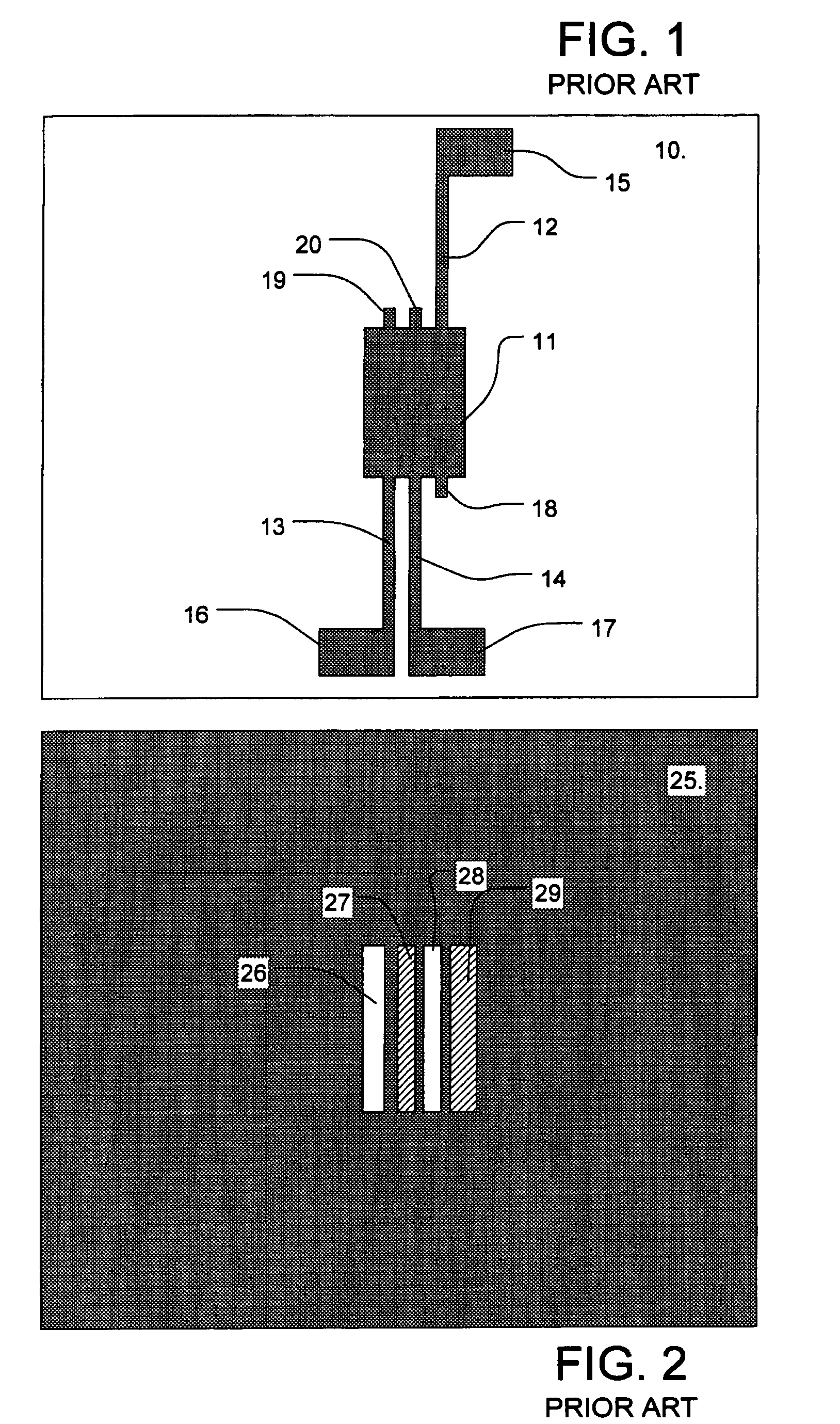
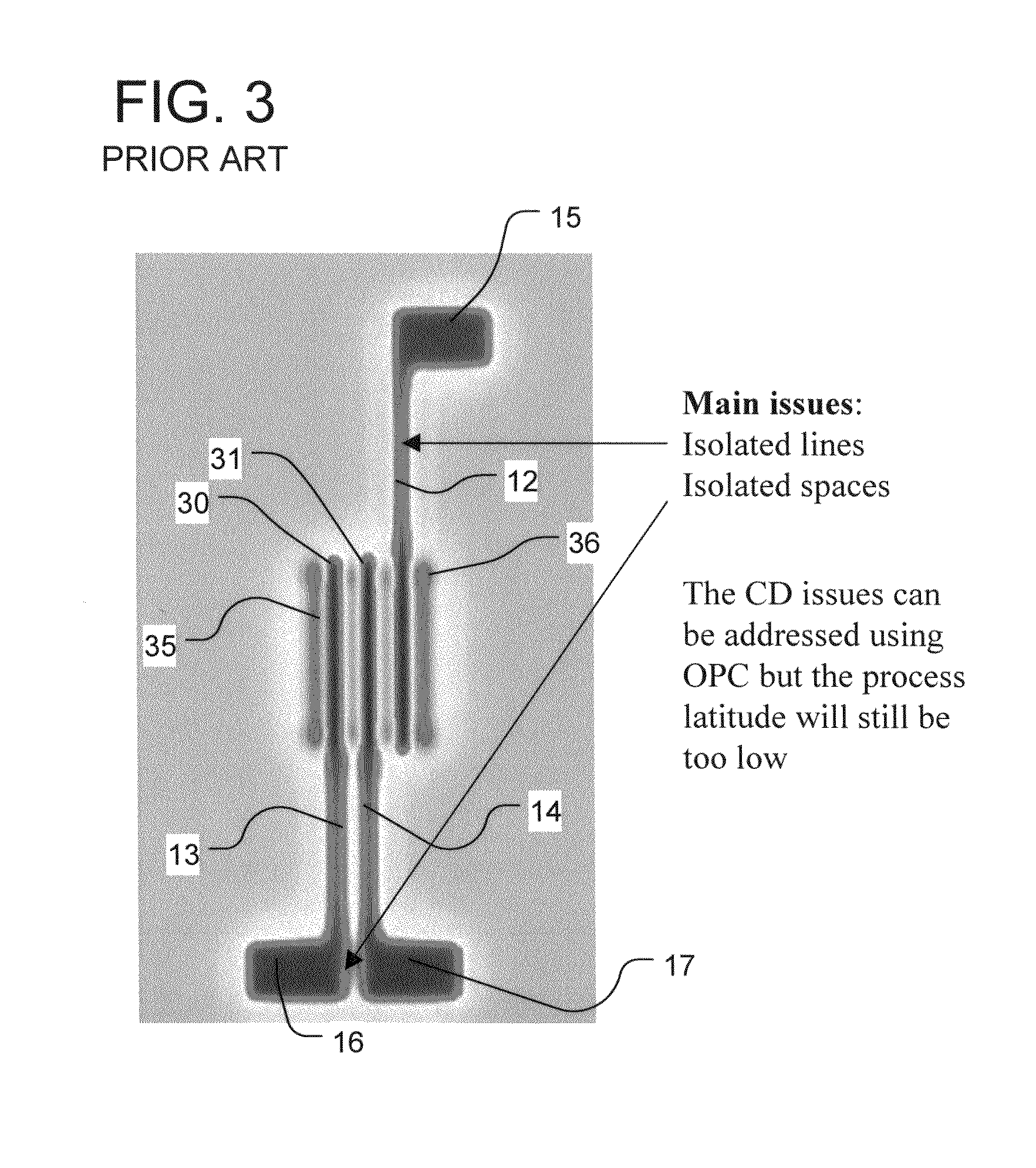
[0043]A detailed description of the present invention is provided with respect FIGS. 1-18. FIGS. 1-3 illustrate problems associated with the layout and manufacturing of small dimension features according to the prior art. FIGS. 4-6 illustrate an approach to improving the layout and manufacturing of the small dimension features shown in FIGS. 1-3 according to the present invention. FIGS. 7-18 illustrate additional features and techniques.

[0044]FIG. 1 shows a binary mask for use in combination with an opaque field phase shift mask as shown in FIG. 2. The binary mask of FIG. 1 includes an opaque feature within a clear field 10. The opaque feature includes a blocking region 11 which corresponds to the features, i.e. transistor gates in an active region of a device, formed using the phase shift structures of FIG. 2. Narrow lines 12, 13 and 14 extend from the blocking region 11 to respective flag shaped elements 15, 16, 17. The narrow lines 12, 13, 14 in this example each extend through t...


PUM

PropertyMeasurementUnit
angleaaaaaaaaaa
180 degree angleaaaaaaaaaa

Abstract

A method extends the use of phase shift techniques to complex layouts, and includes identifying a pattern, and automatically mapping the phase shifting regions for implementation of such features. The pattern includes small features having a dimension smaller than a first particular feature size, and at least one relatively large feature, the at least one relatively large feature and another feature in the pattern having respective sides separated by a narrow space. Phase shift regions are laid out including a first set of phase shift regions to define said small features, and a second set of phase shift regions to assist definition of said side of said relatively large feature. An opaque feature is used to define the relatively large feature, and a phase shift region in the second set is a sub-resolution window inside the perimeter of the opaque feature.

Description

RELATED APPLICATION DATA[0001]The present application is a continuation of application Ser. No. 10 / 244,226 filed 16 Sep. 2002, now U.S. Pat. No. 6,777,141, which application is a continuation-in-part of application Ser. No. 09 / 669,367, filed 26 Sep. 2000 now U.S. Pat. No. 6,541,165 entitled Phase Shift Mask Sub-Resolution Assist Features; which application claims the benefit of prior U.S. Provisional Application No. 60 / 215,938; filed 5 Jul. 2000; entitled Phase Shift Masking for Complex Layouts, invented by Christophe Pierrat, which is incorporated by reference as if fully set forth herein.[0002]The present application is related to U.S. patent application Ser. No. 09 / 669,368, entitled Phase Shift Masking for Intersecting Lines, invented by Christophe Pierrat, filed 26 Sep. 2000, and owned by the same assignee now and at the time of invention, now U.S. Pat. No. 6,524,752 issued 25 Feb. 2003; and also related to U.S. patent application Ser. No. 09 / 669,359, entitled Phase Shift Maskin...

Claims


Application Information

Patent Timeline
Patent Type & Authority Patents(United States)
IPC IPC(8): G03F1/00
CPCG03F1/30G03F1/36
Inventor PIERRAT, CHRISTOPHE
Owner SYNOPSYS INC
Why Eureka
Try Eureka