
Method and apparatus for optimizing operation of a power generating plant using artificial intelligence techniques

a technology of artificial intelligence and power generating plant, applied in adaptive control, process and machine control, instruments, etc., can solve problems such as imbalances in reheat or superheat sections, redistribution/reduction of heat transferred, and heat absorbed across various sections of boilers, so as to achieve optimal performance and improve the accumulation of soot

Active Publication Date: 2009-09-01
GE DIGITAL HLDG LLC
View PDF19 Cites 29 Cited by
  • Summary
  • Abstract
  • Description
  • Claims
  • Application Information

AI Technical Summary

Benefits of technology

The AI-based system optimizes soot cleaning operations, reducing fuel consumption, NOx emissions, and equipment wear by dynamically adjusting soot cleaning strategies, enhancing overall power plant efficiency and stability in response to changing conditions.

Problems solved by technology

Soot and slag buildup causes a redistribution / reduction of the heat transferred, and hence heat absorbed across various sections of the boiler.
In addition, it affects furnace gas flows that, for example, may cause metal temperature hot spots, imbalances in reheat or superheat sections, or possible tube erosion.
This condition, if left uncontrolled, often leads to a heat rate penalty, increased NOx emissions and reduced tube / metal life.
Adverse heat rate impacts arise from numerous factors including, but not limited to: (1) incomplete combustion or related effect, (2) unbalanced steam generation, (3) excessive use of desuperheater sprays, (4) high exit gas temperatures, (5) forced deslagging events, (6) increased gas flow losses, as well as (7) excessive use of soot cleaning energy.
As the boiler sections become excessively slagged, heat transfer ability is impaired which leads to higher temperatures and higher NOx levels.
Incorrect accumulation of soot (i.e., fouling) of the boiler leads to poor efficiencies due to the fact that heat that could normally be transferred to the working transfer medium remains in the flue gas stream and exits to the environment without beneficial use, or transfers its energy in a less desired, less efficient portion of the power generating unit.
This loss in efficiency translates to higher consumption of fuel for equivalent levels of electricity generation, which in turn may produce more gaseous, particulate, and other emissions.
Although extremely efficient, these devices are sensitive to rapid changes in inlet mass concentration as well as total mass loading.
Without extreme care and due diligence, excursions or excessive soot can overload an ESP, resulting in the release of high levels of PM.
Furthermore, the ESP efficiency can be adversely affected by an increase in gas temperature at the point of particulate collection.
These methods result in indiscriminate cleaning of the entire boiler or sections thereof, regardless of whether sections are already clean.
Traditional methods of soot cleaning, even when they are effective in assuring that a boiler is clean, fail to optimize the heat transfer rates therein, so as to maximize its operation relative to emissions and power generating unit performance.
Traditional methods may also lead to accelerated tube failure through erosion, (blowing on clean surfaces), or metal fatigue (creating large temperature differentials when a large layer of soot has built up and is cleaned).
However, the effects of boiler soot cleaning are complex and interrelated with combustion and / or power generating unit characteristics.
There are multiple trade-offs between achieving a cleaner surface and the cost of operating a soot cleaning device.
Thus, main steam and reheat steam temperatures are reduced with an associated cost penalty manifested as an increase in unit heat rate.
Trade-offs occur as furnace walls can become too clean and result in non-optimal steam temperature as a result of excessive heating in the furnace area and lead to either an effect of excessive steam attemperation spray, or conversely insufficient temperatures in one or another steam paths.
Both affects can result from over cleaning or under cleaning of a furnace area.
Under some operating conditions, convective pass cleaning may necessitate excessive desuperheating spray in order to maintain superheat or reheat steam temperatures within operational limits.
This directly results in an increase in unit heat rate.
Simultaneously optimizing the objectives of NOx, PM, heat rate, opacity, or other requirements is difficult and unrealistic for a control room operator to do manually, even more so when that operator is also required to maintain control of the balance of the power generating unit's equipment.
Owing to business demands and regulatory issues, present day boilers are subject to volatile changes in operation and fuel types or blends.
Rule-based systems are only as good as the rules that drive them and established rules alone cannot accommodate the diverse set of operating conditions that may be encountered on a daily basis.
Furthermore, time or rule-based systems alone are not the best answer due to the complexity of the individual components, combinations thereof and the desire to satisfy multiple objectives in a dynamic real-time environment.
While the rule-based systems are an improvement over conventional hard-coded techniques, these techniques do not deal with some of the dynamic and transitional operational characteristics of present day boilers.

Method used


Image

  • Method and apparatus for optimizing operation of a power generating plant using artificial intelligence techniques
  • Method and apparatus for optimizing operation of a power generating plant using artificial intelligence techniques
  • Method and apparatus for optimizing operation of a power generating plant using artificial intelligence techniques

Examples


Embodiment Construction

[0041]It should be appreciated that while an embodiment of the present invention is described herein with reference to a power generating unit that uses coal, the present invention is applicable to boilers used in connection with power generating systems using other combustible fuels and with systems other than power generating units.

[0042]It should also be understood that the various systems described in the illustrated embodiments of the present invention may take the form of computer hardware, computer software, or combinations thereof. The computer hardware may take the form of a conventional computer system including a processor, data storage devices, input devices (e.g., keyboard, mouse, touch screen and the like), and output devices (e.g., display devices such as monitors and printers), or be embodied as part of another computer system.

[0043]The main components of a fossil fuel fired power generating unit will now be briefly described. A typical power generating unit includes...


PUM


Abstract

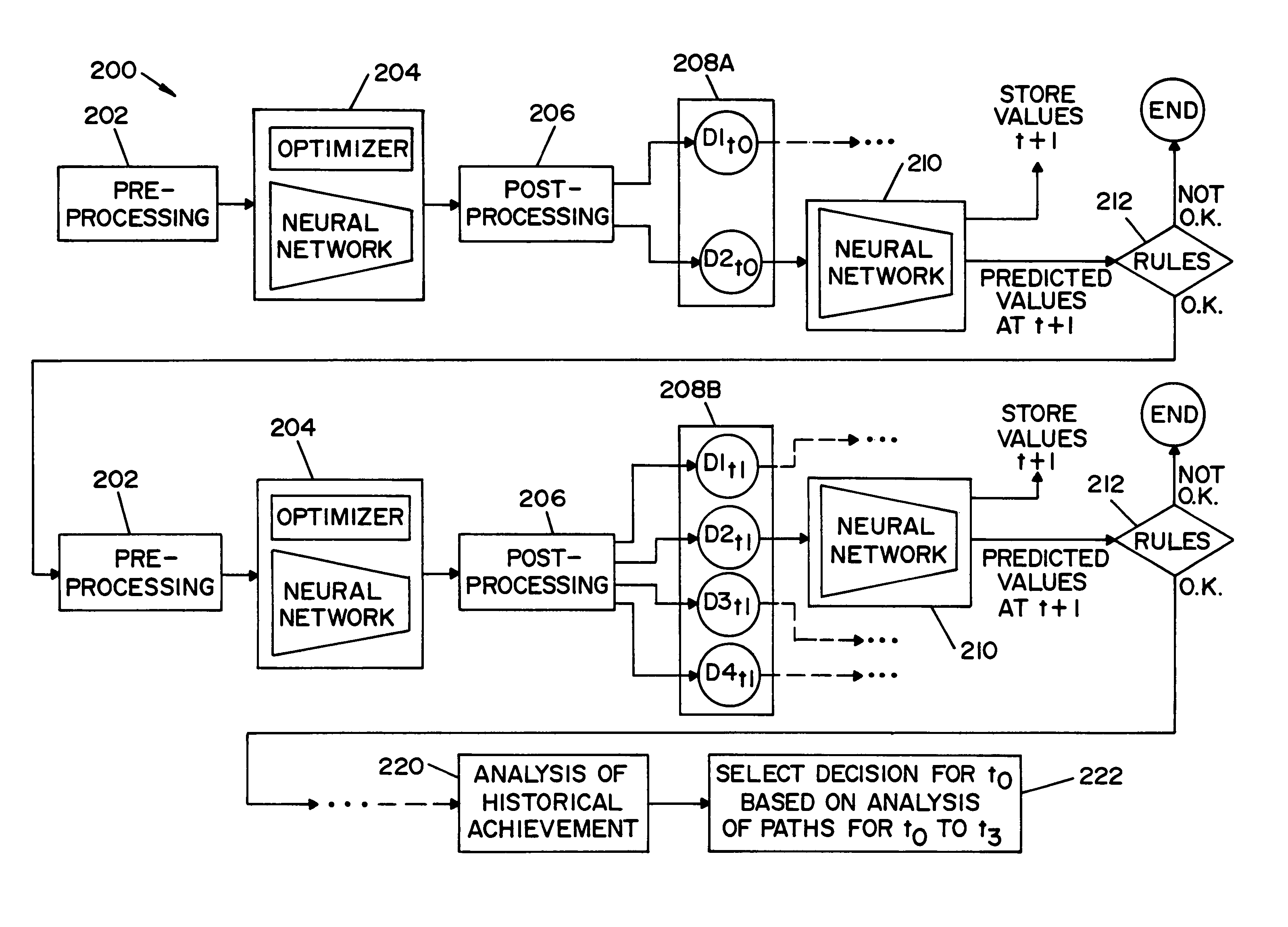
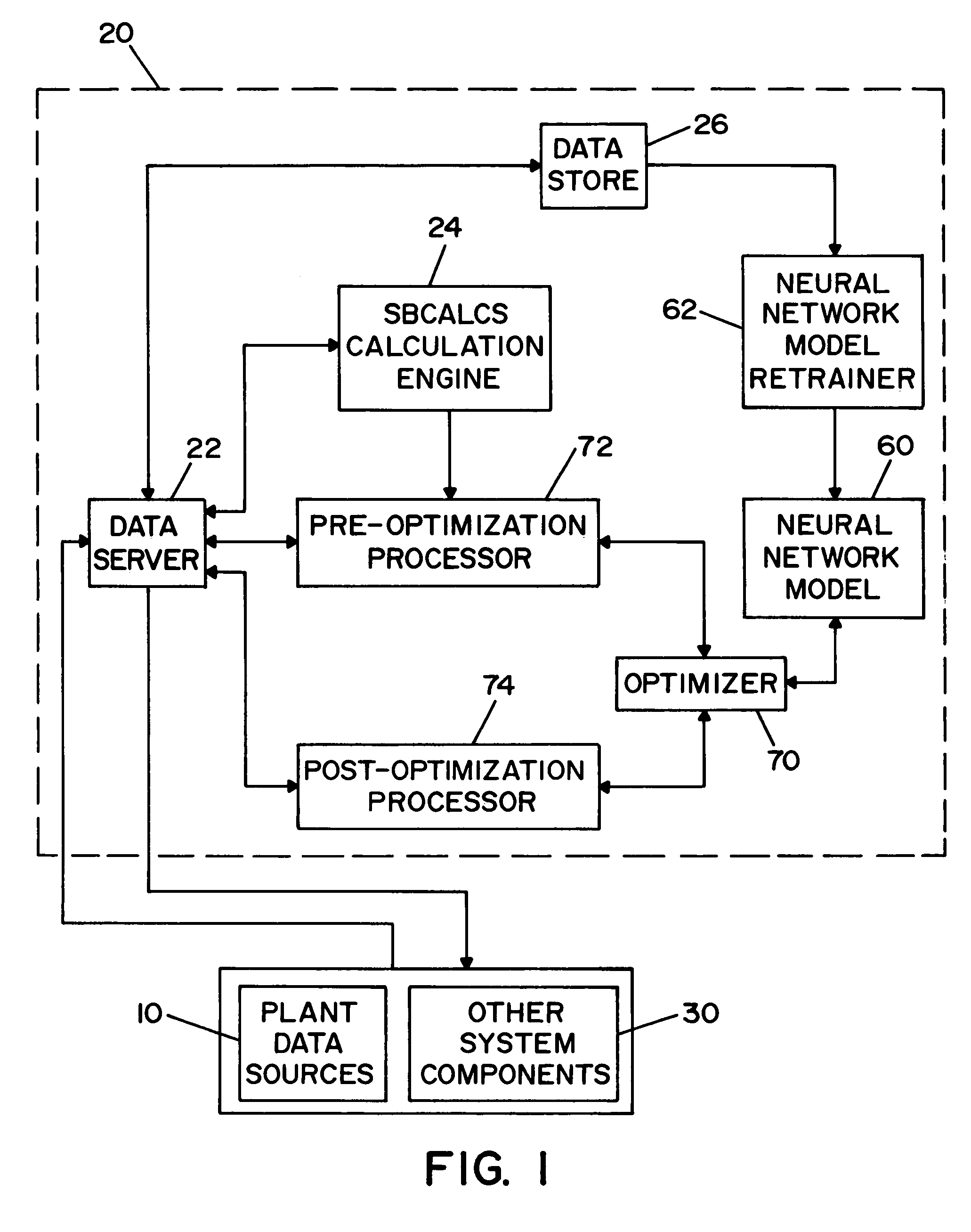
A method and apparatus for optimizing the operation of a power generating plant using artificial intelligence techniques. One or more decisions D are determined for at least one consecutive time increment, where at least one of the decisions D is associated with a discrete variable for the operation of a power plant device in the power generating plant. In an illustrated embodiment, the power plant device is a soot cleaning device associated with a boiler.

Description

STATEMENT OF GOVERNMENT INTEREST[0001]This invention was made with Government support under Contract No. DE-FC26-02NT41425 awarded by the U.S. Department of Energy. The Government has certain rights in the invention, including a paid-up license and the right, in limited circumstances, to require the patent owner to license others on reasonable terms.FIELD OF THE INVENTION[0002]The present invention relates generally to the operation of a power generating plant, and more particularly to a method and apparatus for optimizing the operation of a power generating plant using artificial intelligence techniques.BACKGROUND OF THE INVENTION[0003]In a conventional fossil fuel-fired (e.g., coal-fired) power generating unit a fossil fuel / air mixture is ignited in a boiler. Large volumes of water are pumped through tubes inside the boiler, and the intense heat from the burning fuel turns the water in the boiler tubes into high-pressure steam. The high-pressure steam from the boiler passes into a...

Claims


Application Information

Patent Timeline
Patent Type & Authority Patents(United States)
IPC IPC(8): G05B13/02
CPCG05B13/027
Inventor WROBLEWSKI, DAVIDKATROMPAS, ALEXANDER M.PARIKH, NEEL J.
Owner GE DIGITAL HLDG LLC
Learn More