
Image processing method, image processor, image forming apparatus and memory product

a technology of image processing and memory products, applied in image enhancement, instruments, computing, etc., can solve problems such as non-change of levels, tone gaps, repetition of textures, etc., to reduce the amount of frequency components to be changed, reduce the number of gray levels in inverse-transformed image data, and reduce the number of gray levels

Inactive Publication Date: 2009-08-04
SHARP KK
View PDF5 Cites 14 Cited by
  • Summary
  • Abstract
  • Description
  • Claims
  • Application Information

AI Technical Summary

Benefits of technology

[0019]Another object of the invention is to provide an image processing method, an image processor, an image forming apparatus and a memory product capable of reducing the texture caused in dithering and worms caused in error diffusion and forming a high-quality binary image, quaternary image, etc. by changing, for example, high-frequency components of the image data.
[0059]A computer program stored on a memory product of the present invention comprises the steps of: causing a computer to transform image data including a plurality of color components into spatial frequency components; causing the computer to perform a modification process of changing spatial frequency components in a predetermined frequency domain of a plurality of predetermined color components on the transformed spatial frequency components so that they overlap each other; causing the computer to inverse-transform the spatial frequency components on which the modification process is performed into image data; and causing the computer to reduce the number of gray levels in the inverse-transformed image data, based on a predetermined threshold value.

Problems solved by technology

In the dithering method, however, since the binarization process is performed using dither matrices of the same pattern, regular periodic patterns tend to appear in the image on which the binarization process is performed, and there is the problem of repeated texture which is a characteristic of dithering.
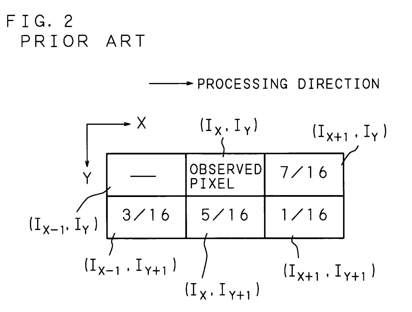
In the error diffusion method, however, since the error is diffused based on the same matrix for each pixel, there is a problem that a worm (portion where dots are partly connected) appears in a highlighted area, and a countermeasure such as, for example, adding noise to the threshold value during binarization has been taken (see, for example, “Threshold Adjusting Technique in Error Diffusion Method”, Toshiaki Kakutani, Journal of the Society of Electrophotography, 1998, Vol. 37, No. 2, p.
However, in a multi-value image such as a quaternary image, since the dot patterns become uniform in an intermediate density region, there is a problem of tone gap (phenomenon in which gray levels change non-continuously).
It is difficult to perfectly prevent a tone gap in the intermediate density region by an algorism of performing quantization by appropriately selecting a plurality of threshold values for use in the intermediate density region.
In the methods disclosed in Japanese Patent Applications Laid-Open No. 2002-10085 and No. 2002-158879, data (frequency components) transformed into a predetermined halftone frequency domain is used, but, since predetermined halftone data is used, there is a problem such as occurrence of texture similarly to the above-mentioned error diffusion method or dithering method.
Further, in the above-mentioned respective conventional techniques, since overlapping of dots of respective colors is not taken into account, not only dots of respective colors are formed on paper in an overlapped fashion, but also a pixel where a dot of any color is not formed tends to appear, and consequently there is a drawback that graininess becomes worse and causes a noisy rough image.
In order to avoid this, for example, a dithering method needs to use different dither matrix for each color, or perform a special process such as determining the presence / absence of dot and shifting the dot position for each color, which causes in increase in the memory capacity and an increase in the amount of calculation, resulting in a problem of an increase in the calculation cost.

Method used


Image

  • Image processing method, image processor, image forming apparatus and memory product
  • Image processing method, image processor, image forming apparatus and memory product
  • Image processing method, image processor, image forming apparatus and memory product

Examples


embodiment 1

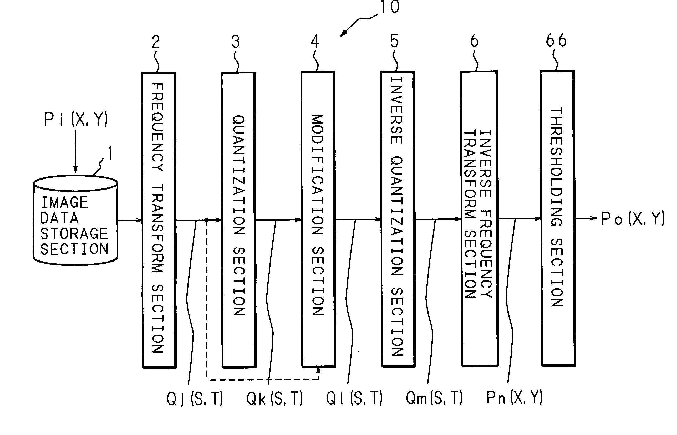
[0093]FIG. 3 is a block diagram showing an example of the structure of a grayscale reproduction processor (image processor) 10 of the present invention. The grayscale reproduction processor 10 is an image processor for generating output image data Po (X, Y) by reducing the number of gray levels (for example, 256 gray levels) of input image data Pi (X, Y) to two levels or four levels. Here, the input image data Pi (X, Y) is pixel data at the Xth pixel position on the Yth line of image data composed of pixels arranged in a two-dimensional matrix of the X-direction (right direction) and Y direction (down direction), and a large number of input image data Pi (X, Y) constitute a two-dimensional image.

[0094]The grayscale reproduction processor 10 comprises: an image data storage section 1 for storing input image data Pi (X, Y); a frequency transform section 2 for transforming the input image data Pi (X, Y) into spatial frequency components Qj (S, T); a quantization section 3 for quantizin...

embodiment 2

[0111]FIG. 8 is a block diagram showing an example of the structure of a grayscale reproduction processor (image processor) 11 of the present invention. Like the grayscale reproduction processor 10 of Embodiment 1 shown in FIG. 3, the grayscale reproduction processor 11 comprises: an image data storage section 1; a frequency transform section 2; a quantization section 3; a modification section 4; an inverse quantization section 5; an inverse frequency transform section 6; and a thresholding section 66. However, the quantization section 3 and modification section 4 are connected in the reverse order to that of Embodiment 1 (FIG. 3).

[0112]In Embodiment 2, the modification section 4 changes the modification region of the spatial frequency components (DCT coefficients) Qj (S, T) transformed in the frequency transform section 2. The modification process is almost the same as that in Embodiment 1, but, in Embodiment 2, since quantization has not been performed by the quantization section ...

embodiment 3

[0114]FIG. 9 is a block diagram showing an example of the structure of a grayscale reproduction processor (image processor) 12 of the present invention. Between the quantization section 3 and modification section 4 of the grayscale reproduction processor 10 of Embodiment 1 shown in FIG. 3, the grayscale reproduction processor 12 further comprises a DC component determining section 7 for determining the magnitude of the DC component of the spatial frequency components (DCT coefficients) Qk (S, T) quantized in the quantization section 3 and controlling the number of 0s, or 1s and −1s changed by the modification section 4, based on the magnitude of the DC component. Here, the number of Is and the number of −1s are the same, and, for example, if the number of 1s and −1s is 2, then the number of 1s is 2 and the number of −1s is also 2. For instance, if the number of 1s and −1s to be changed is 2, then two DCT coefficients in the modification region are changed to 1, and other two DCT coe...


PUM


Abstract

Image data is transformed into spatial frequency components, the transformed spatial frequency components are quantized, a modification process of changing spatial frequency components in a predetermined frequency domain is performed on the quantized spatial frequency components, the spatial frequency components on which the modification process is performed are inverse-quantized, the inverse-quantized spatial frequency components are inverse-transformed into image data, and the number of gray levels in the inverse-transformed image data is reduced to two levels, four levels or other levels based on threshold values. A high-quality binary image, quaternary image, etc. are generated by solving the problem of tone gap which occurs in the vicinity of output levels of the image data and solving the texture caused in dithering and worms caused in error diffusion.

Description

CROSS-REFERENCE TO RELATED APPLICATIONS[0001]This non-provisional application claims priority under 35 U.S.C. §119(a) on Patent Applications No. 2003-273501 filed in Japan on Jul. 11, 2003, No. 2003-334272 filed in Japan on Sep. 25, 2003 and No. 2003-365097 filed in Japan on Oct. 24, 2003, the entire contents of which are hereby incorporated by reference.BACKGROUND OF THE INVENTION[0002]The present invention relates to an image processing method, an image processor, an image forming apparatus and a memory product for reducing the number of gray levels in image data.[0003]For example, when forming a pseudo-grayscale image including halftones by an image forming apparatus of binary output, it is necessary to perform a binarization process for reducing the number of gray levels to two levels while taking into account the grayscale reproducibility. As the binarization method, various methods have been used, such as a method in which a comparison with a threshold value is performed, a di...

Claims


Application Information

Patent Timeline
Patent Type & Authority Patents(United States)
IPC IPC(8): G06K9/36G06T5/00H04N1/405
CPCH04N1/4052H04N19/90H04N19/60
Inventor KATOUGI, TERUMITSUWAKAHARA, SHIROHAMADA, KAZUYUKI
Owner SHARP KK
Learn More