
Battery powered riding floor stripping machine

a technology of floor stripping machine and battery, which is applied in the direction of floor surfacing/polishing machine, carpet cleaner, building repair, etc., can solve the problems of occupying space inside the machine, placing weight over the rear wheels, and reducing the space available for batteries, hydraulic oil tanks and other needed equipment, so as to achieve quick and easy replacement

Active Publication Date: 2009-07-21
NAT FLOORING EQUIP INC
View PDF12 Cites 22 Cited by
  • Summary
  • Abstract
  • Description
  • Claims
  • Application Information

AI Technical Summary

Benefits of technology

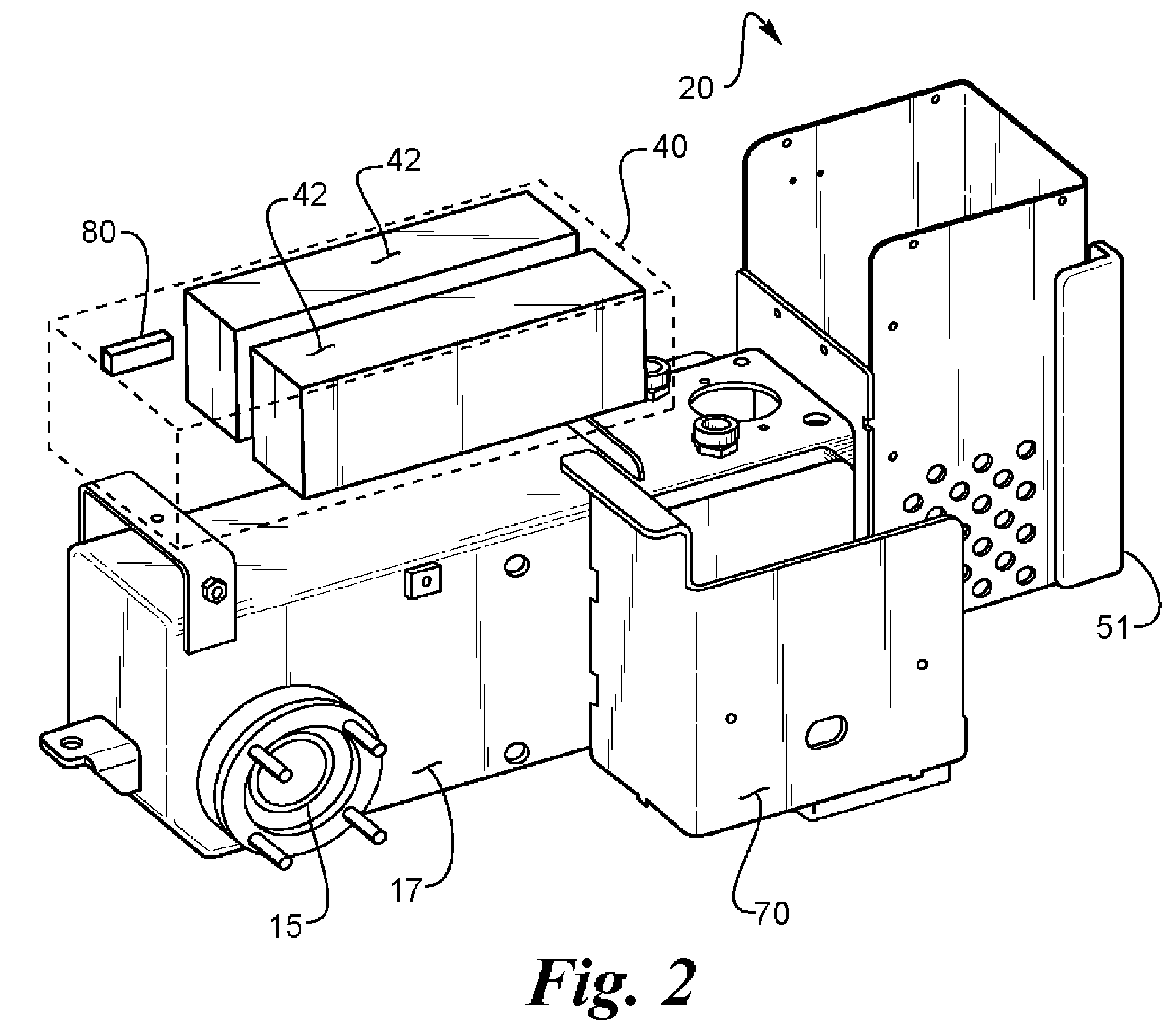
[0011]The battery operated floor stripping machine of the present design has a rear housing with independently controlled hydraulic motor powered rear wheels, a hydraulic tank which encompasses the hydraulic motors, a battery rack and a top cover which hingedly opens for access to the batteries. A seat is attached to the top cover and alternatively a battery rack may be attached to the top cover behind the seat for extra batteries, which can be easily added for extra battery capacity and easily removed for recharging.
[0012]The battery operated floor stripping machine has a blade in front of the motor housing for engaging the floor and removing flooring materials to strip the floor. The blade has an adjustable angle of attack to engage the flooring material at the most efficient angle for the type of flooring material being stripped. To increase the weight on the blade the electric motor is placed between the rear housing and the blade. The motor in front of the rear housing has its own housing and is also easier to work on for maintenance and easier to replace. Further the motor in the front of the rear housing is easier to cool. The hydraulic pump is placed on top of the electric motor to further add weight to the front of the floor stripping machine. The electric motor and hydraulic pump being in a separate housing in front of the rear housing allows for better use of space. The rear housing has less in it, so it can be narrower and not as high for a lower center of gravity. The rear housing can now have larger batteries. The electric motor and hydraulic pump in front of the rear housing allows for narrower more compact design.
[0015]By having large battery packs to power the floor-stripping machine the batteries can power the floor-stripping machine for about four hours before a change is needed. Therefore the machine will only have to be pulled from floor stripping duty one time during a typical eight hour work shift to change the batteries. By having a cart with batteries thereon which can be used to slide the batteries onto when they need recharging and by using a cart to bring recharged batteries to the floor-stripping machine to slide onto the floor-stripping machine the batteries can be quickly and easily changed.
[0017]It is an object of the invention to increase the weight of the floor stripping machine in the front portion near the blade to increase the floor stripping ability.
[0024]It is an object of the invention to provide easy access to the motor for repair, maintenance and replacement.
[0030]It is an object of the invention to provide a battery powered floor-stripping machine with batteries, which can be quickly and easily changed by one person.

Problems solved by technology

This takes up space inside of the machine and places weight over the rear wheels.
The space taken up in the housing on the back portion of the machine by the electric motor, and hydraulic pump decreases the space available for batteries, hydraulic oil tanks and other needed equipment and reduces the ability to cool the electric motor when it is contained inside of the housing in the back portion of the machine.
The electric motor, hydraulic pump and hydraulic motors all inside the housing in the back portion of the machine is harder to work on for maintenance or replacement than a design having the electric motor and hydraulic pump in a separate housing in front of the machine.
Most battery operated machines do not have an eight hour capacity particularly with internally housed batteries.

Method used


Image

  • Battery powered riding floor stripping machine
  • Battery powered riding floor stripping machine
  • Battery powered riding floor stripping machine

Examples


Embodiment Construction

[0038]The floor stripping machine 10 is shown in general in FIG. 1. It has a rear housing 12 with a pair of drive wheels 14 in the rear. The drive wheels 14 are preferably individually controlled and have separate hydraulic motors 15 or alternatively individual electric motors. In the embodiment shown the hydraulic motors 15 are surrounded by tank 17 containing hydraulic fluid. Seat 16 is located on top of rear housing 12. The seat 16 is attached to a hinged cover 18 with the hinge 19 at the back so that the hinged cover swings open backward exposing one or more batteries 42 inside of battery housing 40 on top of tank 17. Placing the batteries 42 over the tank 17 allows easy access to the batteries by pivoting the hinged cover 18, which exposes the batteries 42 for replacing the batteries with new batteries or with recharged batteries.

[0039]A motor housing 20 is placed in the front of rear housing 12 to place the weight of the electric motor 22 near the blade 52. The electric motor ...


PUM

PropertyMeasurementUnit
weight distributionaaaaaaaaaa
poweraaaaaaaaaa
heightaaaaaaaaaa

Abstract

A floor stripping machine having the electric motor and hydraulic pump placed just aft of the blade engages adds weight to the blade and provides for a narrower more compact design with a lower center of gravity for better maneuverability and ease of access to narrow halls, doorways and rooms. A battery powered floor stripping machine may have batteries stored in the housing under the seat and have auxiliary batteries behind the seat on top of the housing for easy of removing the batteries for recharging. Additional batteries and or weights can be used on either side of the housing. In alternative embodiments the floor stripping machine can be remote controlled. Battery management with the auxiliary batteries being recharged during the day allows for eight hours of use. A trunk may store batteries, which can be slid onto a trailing cart to change batteries.

Description

[0001]This application is a continuation-in-part of application Ser. No. 11 / 042,230 filed Jan. 25, 2005, now abandoned.BACKGROUND OF THE INVENTION[0002]1. Field of the Invention[0003]This invention relates to a battery operated floor stripping machine for stripping materials, such as adhesive bonded floor coverings, from floor surfaces, and more particularly to changing batteries in the machine wherein the batteries are a major component of weight distribution and power management by efficient changing of batteries.[0004]2. Description of the Related Art[0005]In one version of battery powered riding floor stripping machine the electric motor, hydraulic pump and hydraulic motors are all inside of the housing in the back portion of the machine. This takes up space inside of the machine and places weight over the rear wheels. Weights therefore have to be added to the front of the machine to increase performance of the blade on the floor. The space taken up in the housing on the back po...

Claims


Application Information

Patent Timeline
Patent Type & Authority Patents(United States)
IPC IPC(8): A47L11/12A47L13/02
CPCE04G23/006
Inventor ANDERSON, MARTIN L.
Owner NAT FLOORING EQUIP INC
Learn More