
System, method and computer program product for handling small aggressors in signal integrity analysis

a signal integrity analysis and aggressor technology, applied in the field of signal integrity analysis, can solve the problems of increasing the densities, increasing the complexity, and affecting the accuracy of interconnection analysis,

Active Publication Date: 2009-07-14
CADENCE DESIGN SYST INC
View PDF14 Cites 159 Cited by
  • Summary
  • Abstract
  • Description
  • Claims
  • Application Information

AI Technical Summary

Benefits of technology

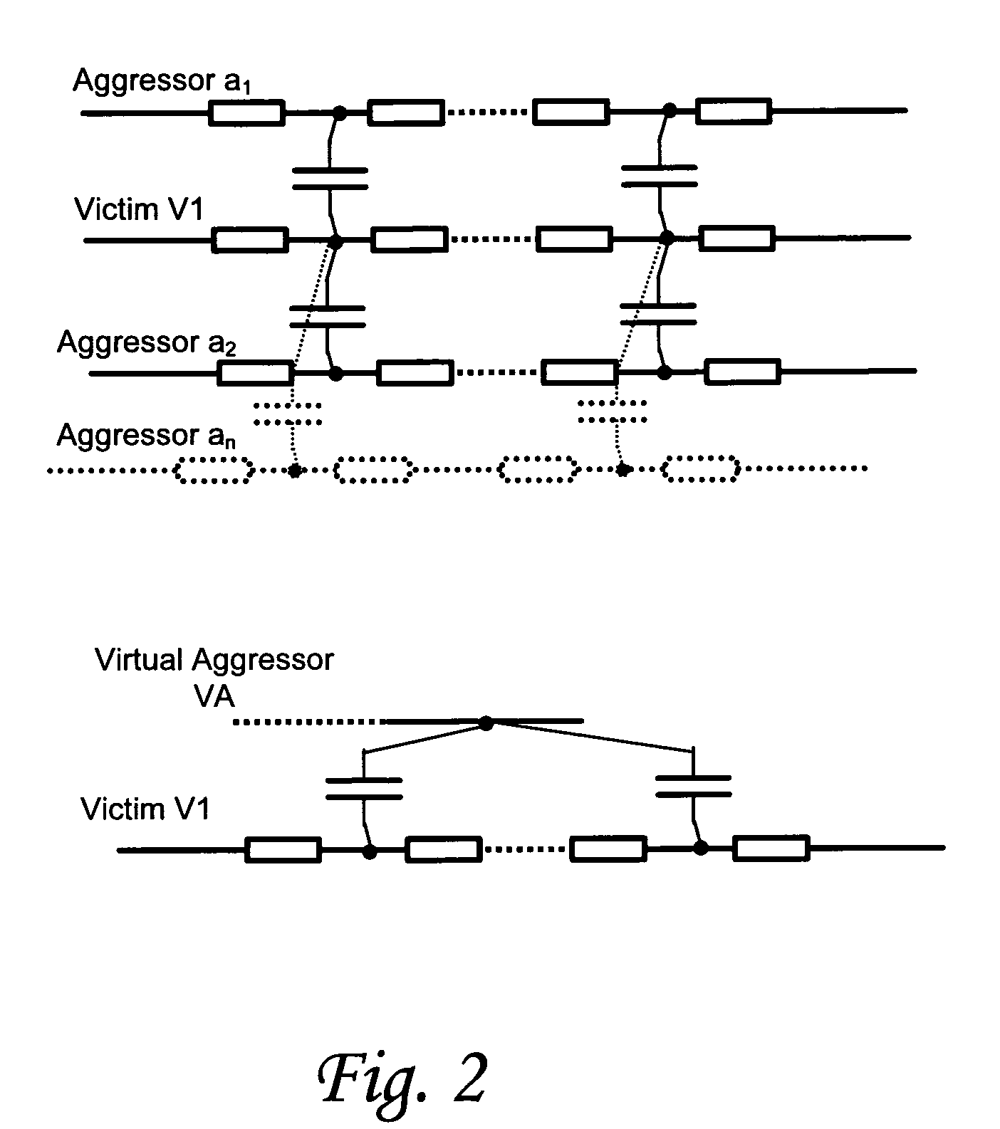
[0023]According to one embodiment of the invention, a method for determining aggressor-induced crosstalk in a victim net of a stage of an integrated circuit design is provided. The method in this embodiment comprises combining a plurality of small aggressor nets to construct a virtual aggressor net, determining a current waveform induced on the victim net by the plurality of small aggressor nets, and modeling a current waveform induced by the virtual aggressor on the victim net based on the contribution of the current waveforms determined for the plurality of smal...

Problems solved by technology

Advances in processing technology and demands for greater complexity at reduced cost and power-consumption points have lead to continual increases in densities.
Another side effect of process advancement is the faster scaling of cell internal delay than the interconnect delay, making accurate analysis of interconnect delay important.
Noise faults may manifest themselves as functional noise faults, or glitches, in which victim nets take incorrect values.
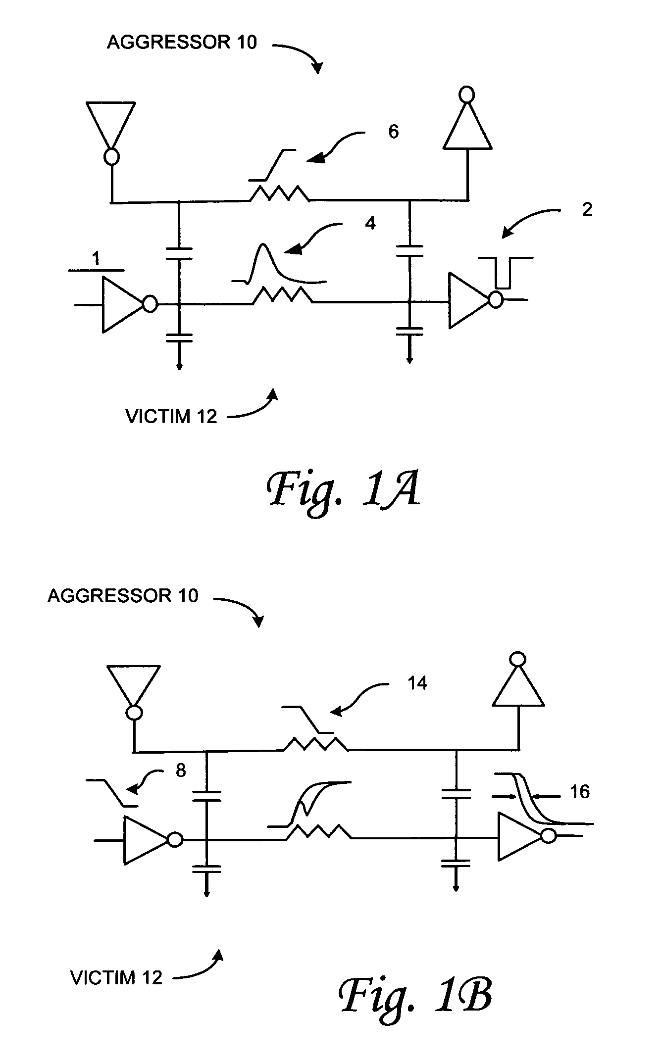
Thus, the crosstalk can have two major effects in modern digital circuits: (i) it can cause a strong glitch on a logically static signal, which may lead to functional fault if the glitch is sampled, and (ii) it can impact arrival time of a signal transition by speeding it up or slowing it down.
Determination of delay in the presence of aggressor-induced noise is a challenging task due to factors such as, (i) delay being sensitive to aggressor / victim alignment, (ii) linear models for switching drivers potentially being inaccurate due to drastic variation of impedance during transition, (iii) effective capacitance principle requiring modification (See, F. Dartu et al, supra), and (iv) waveforms potentially becoming nonmonotonic in the presence of noise, making the conventional metric of delay measurement non-robust.
However, optimization in a multidimensional space of aggressor alignments with each iteration requiring simulation of a nonlinear circuit can be prohibitively expensive.
The crosstalk delay analysis task is further complicated by the potential for a unique waveform response of each receiver of a victim net to a given input transition, such that a WC aggressor alignment for one receiver may not be the same for another.
Another challenge with analyzing a crosstalk induced delay change arises from the potential for crosstalk to distort a victim switching waveform.
A distorted waveform may deviate from the input waveforms used in delay characterization of a receiving gate, resulting in inaccuracy in slew dependent delays in a downstream logic cone.
If the crosstalk impact is severe, the victim waveform may even become non-monotonic (bumpy), the effect of which may not be properly modeled in existing gate delay systems.
This approach is believed to be too conservative and inaccurate to be successfully used for modern design constraints.
However, since the noise wave was computed for a quiet victim driver and not a switching one, the alignment used in the mentioned studies could be inaccurate.
However, there is no teaching of how such current model is to be integrated in a flow of crosstalk delay change analysis.
Unfortunately, the non-monotonic waveforms of FIG. 3A result in a ‘cliff’ in the curve of FIG. 3B methodology.
This prior methodology is not robust because even a relatively small change in a circuit parameter (e.g., driver size, supply voltage, etc) and / or aggressor alignment on a particular victim net can result in a disproportionate change in measured victim signal delay due to such cliff.
Both forms of signal integrity analysis can be computationally costly, and often affect the time-to-market characteristics of design methodology.
The most expensive parts of a signal integrity analysis tend to be (i) RC reduction and (ii) solving the reduced network.
At the same time, the initial implementation of VA in CeltIC suffered from several significant drawbacks resulting in additional inaccuracy of the analysis.
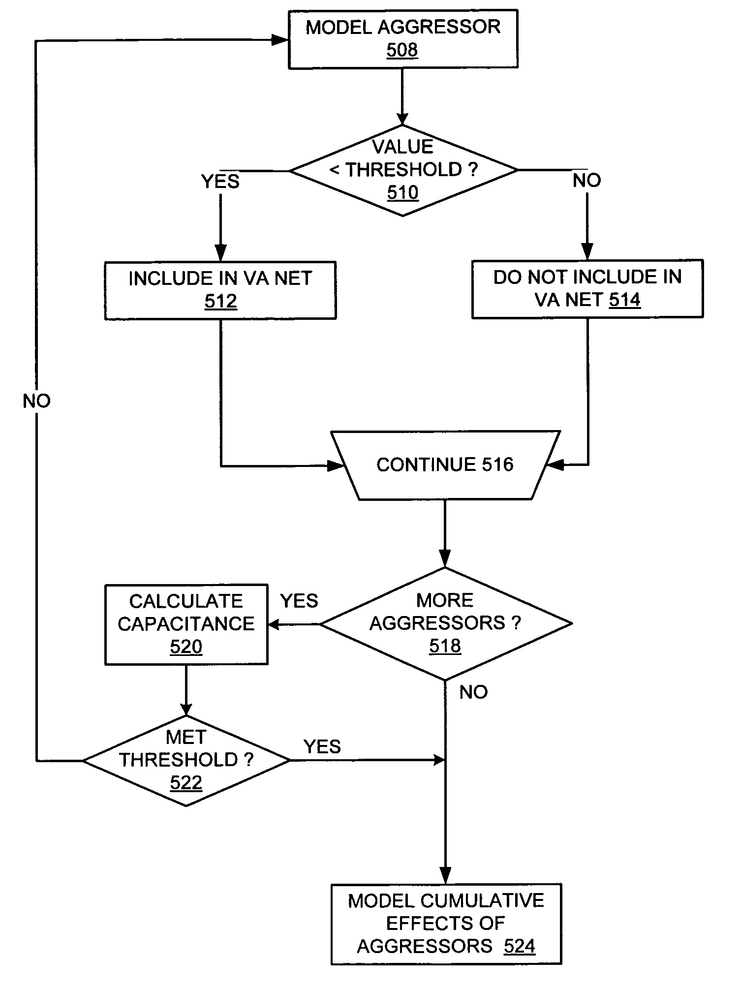
Because the timing restrictions on transitions on the aggressor nets can limit the impact an aggressor has on the victim, conventional virtual aggressor methodologies apply timing window limitations to the capacitive modification process.
However, because timing window limitations are calculated in advance, they do not take into account the dynamic nature of such limitations.
As such, they can become overly pessimistic and expensive.

Method used


Image

  • System, method and computer program product for handling small aggressors in signal integrity analysis
  • System, method and computer program product for handling small aggressors in signal integrity analysis
  • System, method and computer program product for handling small aggressors in signal integrity analysis

Examples


Embodiment Construction

[0047]The present invention provides a novel method and apparatus for crosstalk analysis for use during integrated circuit design, evaluation and testing. Crosstalk between a victim net and an aggressor net can induce a signal delay change or other unwanted behavior in the victim net. The following description is presented to enable any person skilled in the art to make and use the invention. The embodiments of the invention are described in the context of particular applications and their requirements. These descriptions of specific applications are provided only as examples. Various modifications to the preferred embodiments will be readily apparent to those skilled in the art, and the generic principles defined herein may be applied to other embodiments and applications without departing from the spirit and scope of the invention. Thus, the present invention is not intended to be limited to the embodiments shown, but is to be accorded the widest scope consistent with the principl...


PUM


Abstract

A method, system and computer program product for determining aggressor-induced crosstalk in a victim net of a stage of an integrated circuit design is provided. The methodology can include combining a plurality of aggressor nets to construct a virtual aggressor net, determining a current waveform induced on the victim net by the plurality of small aggressor nets, and modeling a current waveform induced by the virtual aggressor on the victim net based on the contribution of the current waveforms determined for the plurality of small aggressor nets. In a further embodiment, the methodology can also comprise evaluating an effect of an aggressor net on a victim net; and including that aggressor net in the virtual aggressor net if its effect is below a predetermined threshold. The effect evaluated by the methodology can, for example, be the height of a glitch induced on the victim net by a transition in the aggressor net. Additionally, the aggressor net can be included in the virtual aggressor net if the height of the glitch it induces on the victim net is less than a predetermined factor of the supply voltage. Switching probability can be used to compute a 3-sigma capacitance value, and this value can be used to limit the number of small aggressors included in the virtual aggressor net. The combined currents of the aggressor in the virtual aggressor net can be modeled using a piece-wise linear analysis.

Description

CROSS REFERENCE TO RELATED APPLICATIONS[0001]This is a continuation in part of U.S. Ser. No. 10 / 735,123, filed on Dec. 12, 2003, which claims the benefit of priority under 35 U.S.C. § 119(e) to 60 / 504,127, filed on Sep. 19, 2003, and this application claims the benefit of priority under 35 U.S.C. § 119(e) to U.S. provisional application Ser. No. 60 / 752,518, filed on Dec. 20, 2005. The contents of these applications are incorporated by reference herein.FIELD OF THE INVENTION[0002]The present invention relates generally to signal integrity analysis, and more particularly to a system and method for handling small aggressors in signal integrity analysis.BACKGROUND OF THE INVENTION[0003]Advances in processing technology and demands for greater complexity at reduced cost and power-consumption points have lead to continual increases in densities. As geometries scale signal paths become closer together, a side effect of this scaling is that coupling capacitance between wires becomes the dom...

Claims


Application Information

Patent Timeline
IPC IPC(8): G06F17/50
CPCG06F17/5036G06F17/5031G06F30/3312G06F30/367
Inventor BAI, XIAOLIANGKELLER, IGOR
Owner CADENCE DESIGN SYST INC
Learn More