
Writing method and writing apparatus of charged particle beam, positional deviation measuring method, and position measuring apparatus

a writing method and charge particle technology, applied in the field of charge particle beam writing method, charge particle beam writing apparatus, position measurement apparatus, position measurement apparatus, can solve the problems of sub-resolution assistant features for correcting optical proximity effects that may sub-resolution assistant features become complicated in proportion, etc., to achieve highly accurate measurement of positional deviation and enhance the effect of cleanliness in the apparatus

Active Publication Date: 2009-06-30
NUFLARE TECH INC
View PDF9 Cites 10 Cited by
  • Summary
  • Abstract
  • Description
  • Claims
  • Application Information

AI Technical Summary

Benefits of technology

This approach enables accurate and reproducible pattern writing on EUV masks by correcting positional deviations based on backside topography, ensuring the cleanliness of the chuck surface and improving the precision of the pattern written on the EUV mask, even without the use of electrostatic chucks.

Problems solved by technology

However, in such exposure technique, it is assumed that sub-resolution assistant features for correcting an optical proximity effect may become complicated.
The sub-resolution assistant features become complicated in proportion as the influence of an aerial image becomes large.
Furthermore, there is also a very big problem concerning the way to inspect sub-resolution assistant features on a mask.
Developing new lithography technique with a light of 157 nm has been given up due to lack of lens material for the optics used for image shrinking and transferring.
Moreover, when fabricating a master EUV mask, it is difficult to predict total deformations of a substrate in the step of forming a reflective film, or in the process of patterning.
It is also very difficult to meet the guidelines of electro-static chucks with precision and accuracy, described in the SEMI standard (SEMI P40-1103), and furthermore to check the chucks being met the specifications.
In the case of employing the method of the electrostatic chuck, etc. in which the area of the surface contacting with a mask is large, there is much possibility of the electric conduction film on the backside being damaged by friction etc. generated at a contact part and such damaged film becoming a particle.
Moreover, if a particle exists on the backside of an EUV mask, there is concern to fail to meet the requirements of image positional accuracy of the pattern because of a local deformation of the EUV mask caused by the mask backside not having a tight contact in and around the particle.
However, to retain and manage the chuck surface to be such clean is very difficult.
Although there is a possibility of the resist partially going around to the side and the backside of the substrate at the time of the application, it is very difficult to remove the residues and adhesive substances, such as resist, on the side or the backside without any influence on the resist of the mask surface.
However, even when the baking process is performed, the resist being a polymer film has a feature of easily damaged and removed.
In this situation, it is easily considered that the resist which unexpectedly goes around to the side or the backside may become a cause of particulate contamination in the pattern writing apparatus because such resist removes or attaches to a contact portion.
Therefore, it becomes difficult to retain the chuck surface in a clean condition.
As a result, since the particles on the electrostatic chuck surface are contacted with the mask backside, keeping the mask backside to be an ideal plane becomes difficult.
Therefore, a problem may arise in the reproducibility when reproducing, by calculation, a state of the substrate backside being corrected to be a desired curved or flat surface.
However, it is very difficult to equip this measuring instrument on the pattern writing apparatus because of structure restrictions of the apparatus.
Accordingly, even if there is a measuring instrument which can be equipped on the pattern writing apparatus in consideration of the structure restrictions, there is concern that resolution of the measuring device may not enough.
As mentioned above, there is a problem that when using an electrostatic chuck for holding an EUV mask in order to write thereon in the position measuring apparatus, making the electrostatic chuck which fulfills specifications in the guidelines advocated by SEMI is very difficult.
Moreover, even if it becomes possible to use the electrostatic chuck which fulfills the specifications, there is a problem, such as a particle management caused by resist peculiar to the pattern writing apparatus, namely the resist different from that of the exposure apparatus.

Method used


Image

  • Writing method and writing apparatus of charged particle beam, positional deviation measuring method, and position measuring apparatus
  • Writing method and writing apparatus of charged particle beam, positional deviation measuring method, and position measuring apparatus
  • Writing method and writing apparatus of charged particle beam, positional deviation measuring method, and position measuring apparatus

Examples


embodiment 1

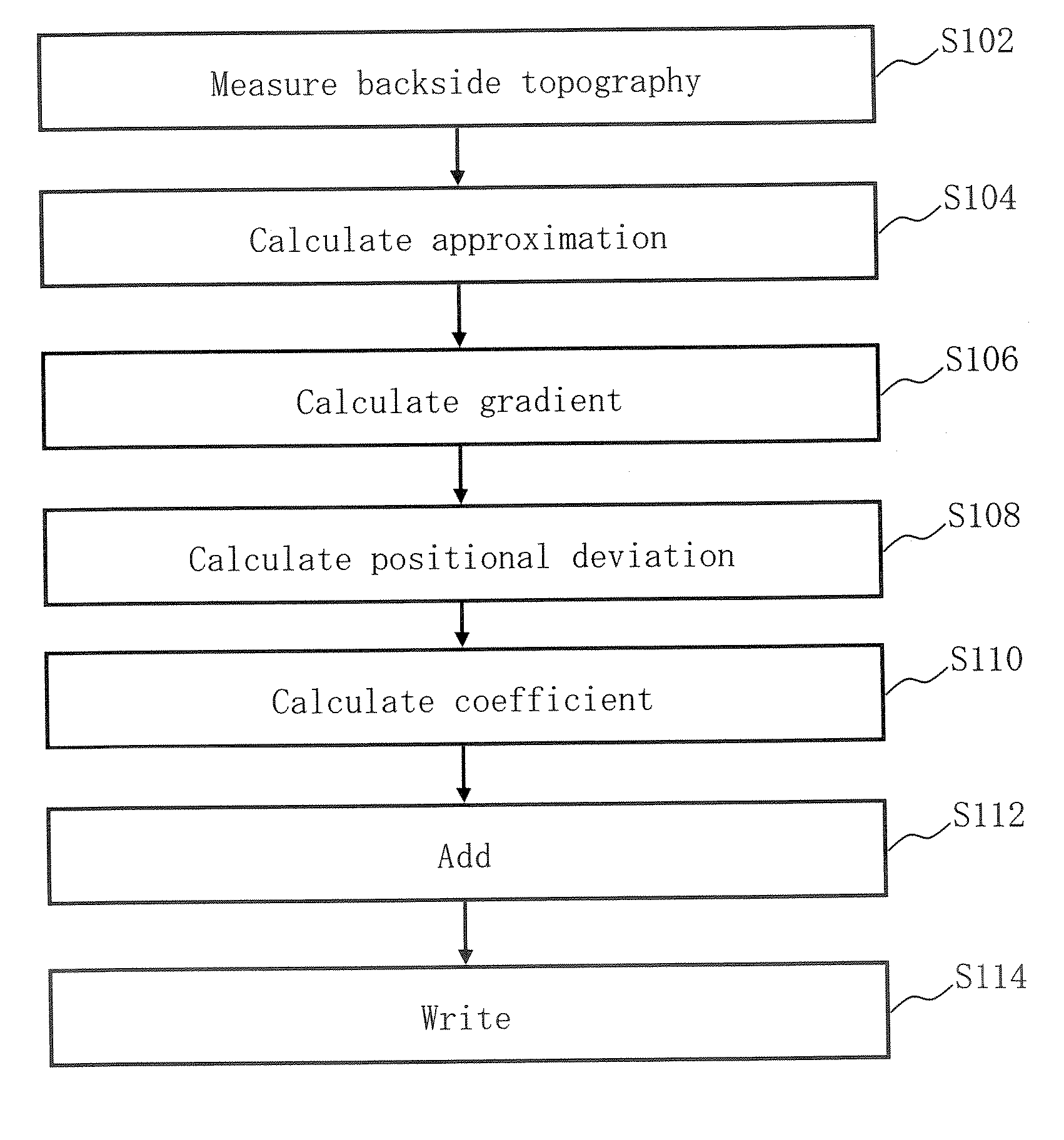
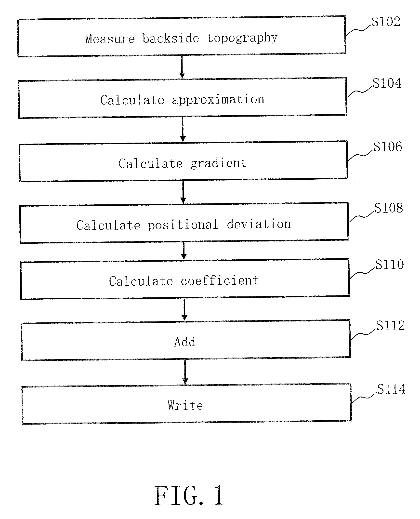
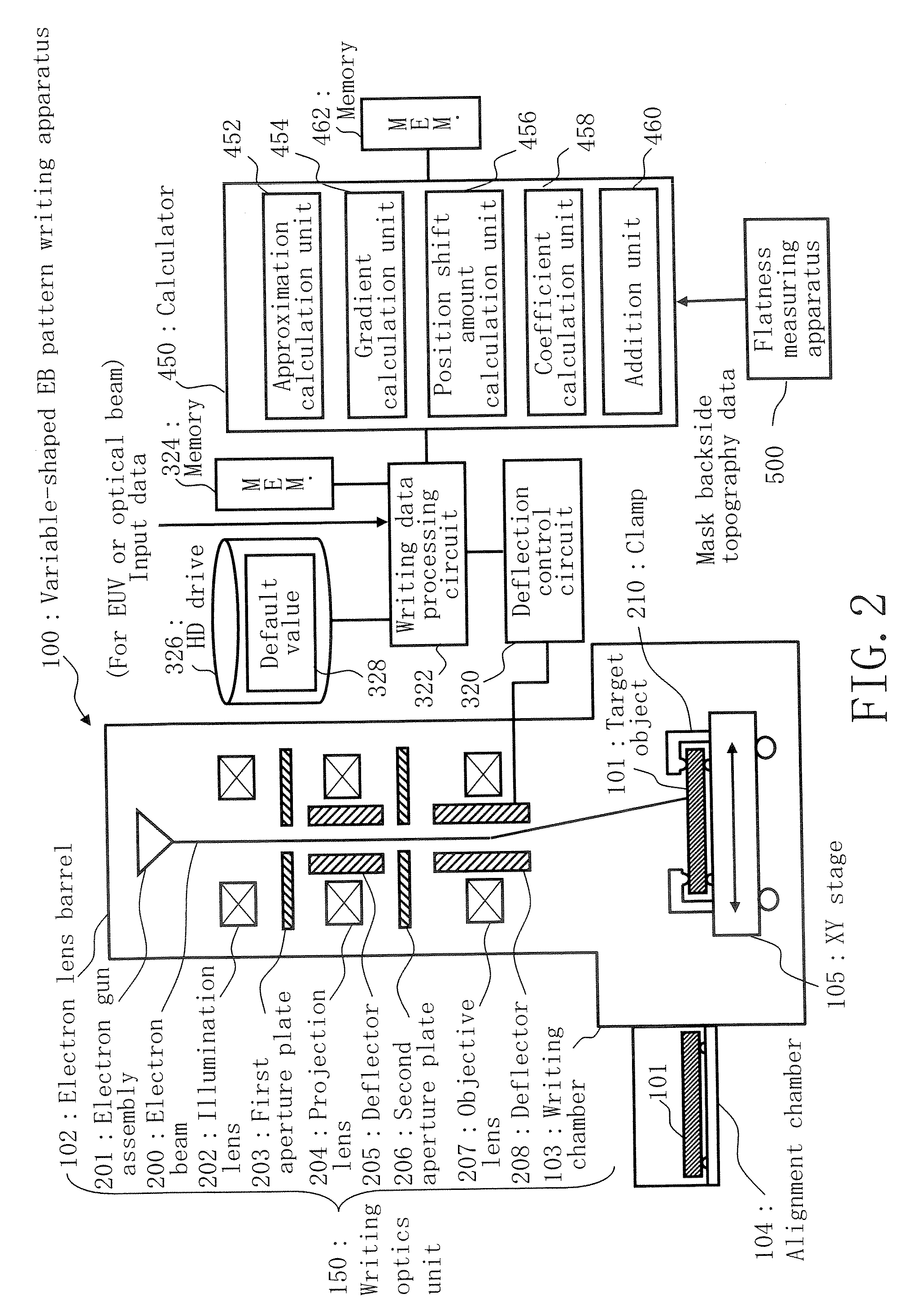
[0056]When writing on an EUV mask, measurement is performed as follows before a writing JOB registration, in Embodiment 1. That is, influence of the mask gravity sag is eliminated beforehand from the substrate backside topography of an EUV mask, and only the backside topography peculiar to the substrate is measured by a flatness measuring apparatus. Furthermore, when the measurement is executed, a high-precision measuring apparatus using an interferometer which is not incorporable in the pattern writing apparatus is utilized. Thereby, the topography of the backside of the mask can be measured sufficiently precisely.

[0057]A positional deviation of a pattern is calculated based on the measured backside topography information peculiar to the substrate. At the time of a registration of writing JOB, the positional deviation, calculated as one of parameters peculiar to the substrate, is inputted. Then, the coordinate system of the writing pattern is corrected based on the calculated posit...

embodiment 2

[0094]In Embodiment 1, the mask pattern writing apparatus capable of executing a pattern positional deviation correction highly accurately, with sufficient reproducibility, at the time of EUV mask writing, based on topography information on the substrate backside has been explained. When evaluating position accuracy of a mask pattern written by such mask pattern writing apparatus, and when evaluating writing performance of such mask pattern writing apparatus, which can be obtained from the written mask, a position accuracy evaluation apparatus is used which can select an electrostatic chuck or a three-point support method as a holding system of the substrate. In Embodiment 2, the position measuring apparatus that can select the electrostatic chuck or the three-point support method will be explained.

[0095]FIG. 13 is a schematic diagram showing a structure of a position measuring apparatus described in Embodiment 2. As shown in the figure, a position measuring apparatus 600 includes a...

embodiment 3

[0115]In Embodiment 2, a test mask with at least two kinds of test pattern is prepared for evaluating position accuracy of a mask pattern written by a mask pattern writing apparatus capable of executing a positional deviation correction highly accurately with sufficient reproducibility, based on the topography information on the substrate backside, and evaluating writing performance of the mask pattern writing apparatus obtained based on the written mask.

[0116]One test pattern group is measured by a measuring apparatus which eliminates the influence of the mask gravity sag from the substrate backside topography before writing JOB registration and is not provided in the pattern writing apparatus. In this case, a positional deviation amount of the pattern is calculated based on the backside shape information peculiar to the substrate, and is read as one of parameters peculiar to the substrate at the time of writing registration. In this way, the deviation amount of the test pattern gr...


PUM


Abstract

A charged particle beam writing method includes measuring a topography of a backside of a substrate without an influence of a gravity sag, calculating a first positional deviation amount of a pattern written on a frontside of the substrate in a case of the backside of the substrate having been corrected to be flat, based on the the backside topography of the substrate, calculating a first coefficient of a first approximate expression indicating a positional deviation correction amount for correcting the first positional deviation amount, based on the first positional deviation amount, adding the first coefficient to a second coefficient of a second approximate expression indicating a positional deviation correction amount for correcting a second positional deviation amount of the pattern written on the frontside of the substrate in a case of the backside of the substrate having not been corrected to be flat, and writing the pattern on the frontside of the substrate utilizing a charged particle beam, based on one of a positional deviation correction amount obtained by a third approximate expression indicating a positional deviation correction amount using a third coefficient obtained as a result of the adding, and the positional deviation correction obtained by the second approximate expression.

Description

CROSS-REFERENCE TO RELATED APPLICATION[0001]This application is based upon and claims the benefit of priority from prior Japanese Patent Application No. 2005-320300 filed on Nov. 4, 2005 in Japan, the entire contents of which are incorporated herein by reference.BACKGROUND OF THE INVENTION[0002]1. Field of the Invention[0003]The present invention relates to a charged particle beam writing method, a charged particle beam writing apparatus, a positional deviation measuring method, and a position measuring apparatus, and more particularly, for example, relates to a writing method and a writing apparatus for writing a pattern on an EUV (Extreme Ultra Violet) mask using variably-shaped electron beams, and a method and an apparatus for measuring a positional deviation amount of a written pattern on the EUV mask.[0004]2. Related Art[0005]In recent years, circuit line widths of semiconductors are becoming narrower and narrower with an increase in pattern density. In order to precisely make ...

Claims


Application Information

Patent Timeline
Patent Type & Authority Patents(United States)
IPC IPC(8): G03B27/42
CPCB82Y10/00B82Y40/00G03F7/70708G03F7/70783H01J37/3174H01J2237/31798G03F7/2059G03F7/70716
Inventor YOSHITAKE, SHUSUKETAMAMUSHI, SHUICHI
Owner NUFLARE TECH INC
Learn More