
Apparatus, methods and articles of manufacture for signal correction using adaptive phase re-alignment

a technology of adaptive phase and signal correction, applied in the field of electromagnetic wave processing, can solve problems such as system errors in system errors in the phase of output signals from errors, and difficulty in correcting errors that occur during the processing of electromagnetic waves and signals (hereinafter “waves”), so as to reduce the error component

Inactive Publication Date: 2009-06-23
PINE VALLEY INVESTMENTS INC
View PDF37 Cites 49 Cited by
  • Summary
  • Abstract
  • Description
  • Claims
  • Application Information

AI Technical Summary

Benefits of technology

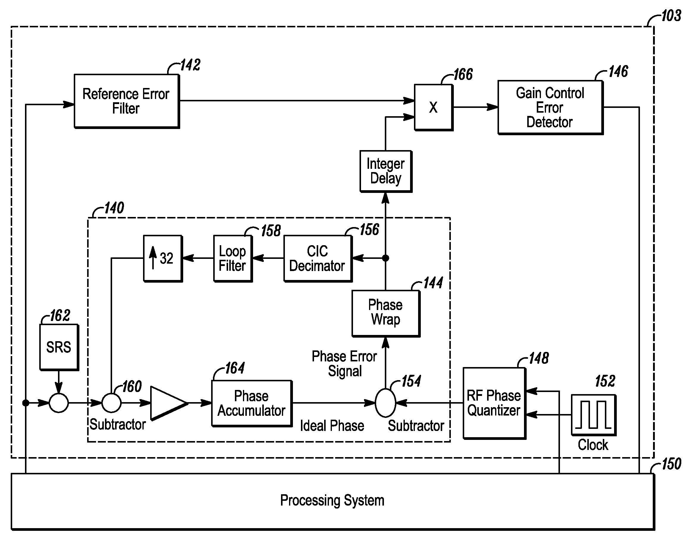
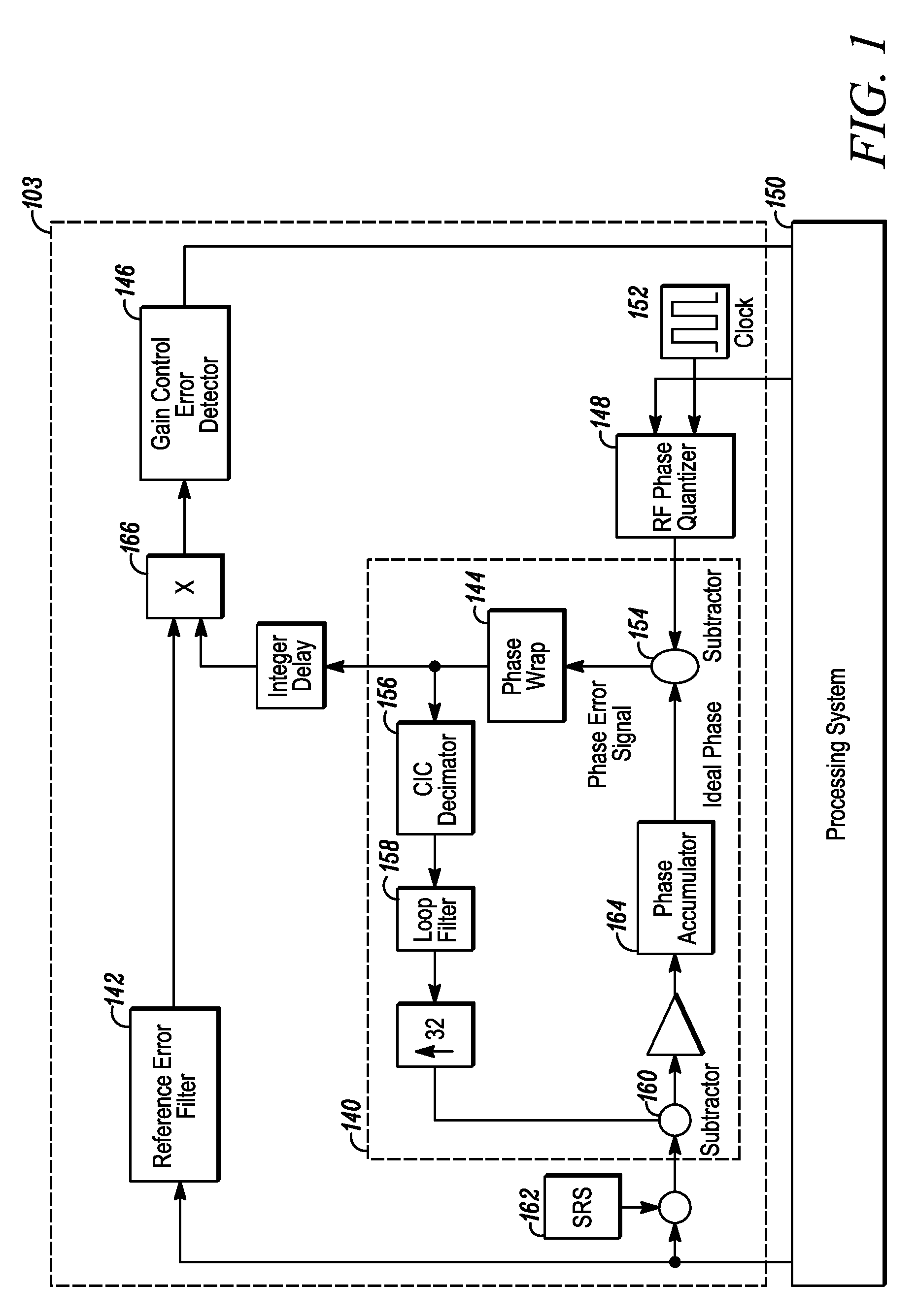
[0006]Embodiments of the invention include apparatus, methods and articles of manufacture for automatically adapting electromagnetic waves during signal processing. The invention may include a system for adaptively re-aligning a modulated output signal having an error component by generating a reference phase signal using a phase input signal; generating a sample phase signal from the output signal; comparing the reference and sample signals; and adaptively re-aligning any difference between the reference and sample signals to substantially reduce the error component.

Problems solved by technology

Correcting errors that occur during the processing of electromagnetic waves and signals (hereinafter “waves”) is sometimes difficult.
Each of these systems may produce errors in the processed signal, however, due to errors that may be introduced into some of the characteristics of the electromagnetic wave during signal processing.
For example, in phase modulation systems, errors may occur in the phase of the output signal from errors introduced during the modulation process.
Calibrating the processing system in this way requires that a system be taken out of service or causes delay and expense in manufacturing the system.

Method used


Image

  • Apparatus, methods and articles of manufacture for signal correction using adaptive phase re-alignment
  • Apparatus, methods and articles of manufacture for signal correction using adaptive phase re-alignment
  • Apparatus, methods and articles of manufacture for signal correction using adaptive phase re-alignment

Examples


Embodiment Construction

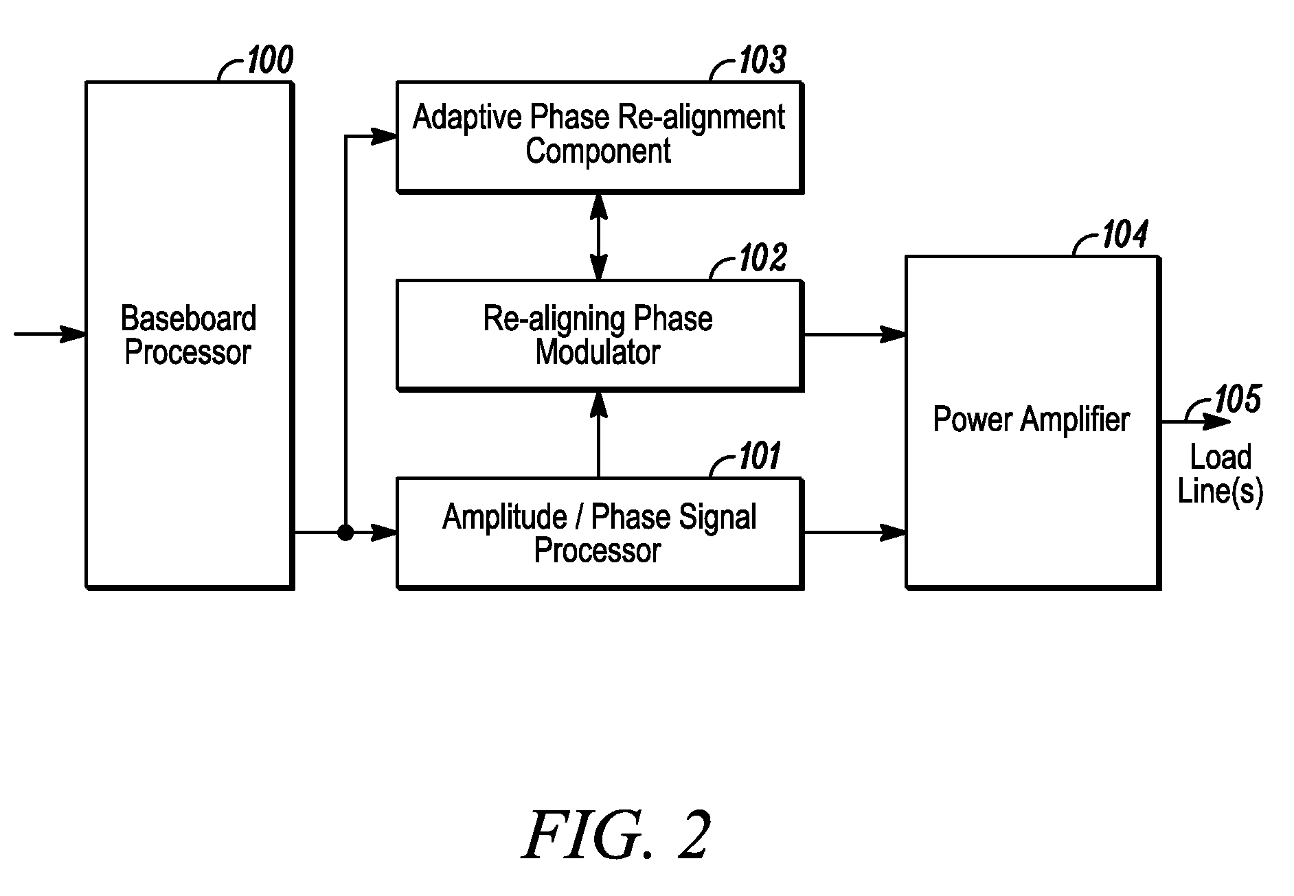
[0013]Embodiments of the invention include apparatus, methods and articles of manufacture for adaptively correcting electromagnetic waves during signal processing. For illustration purposes, one embodiment comprises an adaptive phase re-alignment component tailored for tightly matching an input signal to a wideband phase modulator to predetermined wave characteristics. The system disclosed herein may be used, however, with a wide range of wave processing systems and is not limited to phase correction or phase modulation systems. The system may also be used in a wide range of applications, such as, for example, receivers, transducers, and the like, and is not limited to transmitters.

[0014]The term “signal” as is used herein should be broadly construed to include any manner of conveying data from one place to another, such as, for example, an electric current or electromagnetic field, including without limitation, a direct current that is switched on and off or an alternating-current ...


PUM


Abstract

The invention is directed to a system for adaptively re-aligning a modulated output signal having an error component by generating a reference phase signal using a phase input signal; generating a sample phase signal from the output signal; comparing the reference and sample signals; and adaptively re-aligning any difference between the reference and sample signals to substantially reduce the error component. The invention may incorporate a sampling circuit for sampling the output signal to generate the sample signal; a digital phase locked loop for combining the phase input signal with a carrier wave to generate the reference signal and comparing them to generate a phase error signal; a reference filter for generating reference phase error information; a combining circuit for combining the phase error signal with the reference phase error information to generate a correction signal; and an adaptive gain control circuit for adaptively controlling gain in the correction signal to generate a final estimated error used to re-align the output signal with the phase input signal.

Description

FIELD OF THE INVENTION[0001]The invention relates generally to electromagnetic processing, and more particularly, the invention relates to signal correction using adaptive phase re-alignment.BACKGROUND OF THE INVENTION[0002]Correcting errors that occur during the processing of electromagnetic waves and signals (hereinafter “waves”) is sometimes difficult. These waves may be used for many different purposes. For example, they may be processed in order to convey intelligence, such as by attenuating and / or amplifying electromagnetic wave characteristics, for instance, as is seen when modulating amplitude, frequency or phase of an electrical current or radio frequency (RF) wave to transmit data. As another example, power may be conveyed along a wave in a controlled fashion by attenuating and / or amplifying electromagnetic wave characteristics, such as is seen when modulating voltage or current in a circuit. Moreover, the uses may be combined, such as when intelligence may be conveyed thr...

Claims


Application Information

Patent Timeline
Patent Type & Authority Patents(United States)
IPC IPC(8): H04L25/03H04L27/00H04L27/20H04L27/26
CPCH04L27/20H04L27/2626H04L2027/0018H04L2027/0053H04L2027/0067
Inventor YANG, YONGWENMOY, CAROLDIVINCENZO, CHRISTINE
Owner PINE VALLEY INVESTMENTS INC
Learn More