Temperature detection circuit and semiconductor device
a temperature detection circuit and semiconductor technology, applied in the direction of heat measurement, instruments, measurement devices, etc., can solve the problems of high power consumption of circuits such as power ics, chip failure, temperature rise, etc., and achieve the effect of removing the error component of the temperature characteristic of the diod
- Summary
- Abstract
- Description
- Claims
- Application Information
AI Technical Summary
Benefits of technology
Problems solved by technology
Method used
Image
Examples
first embodiment
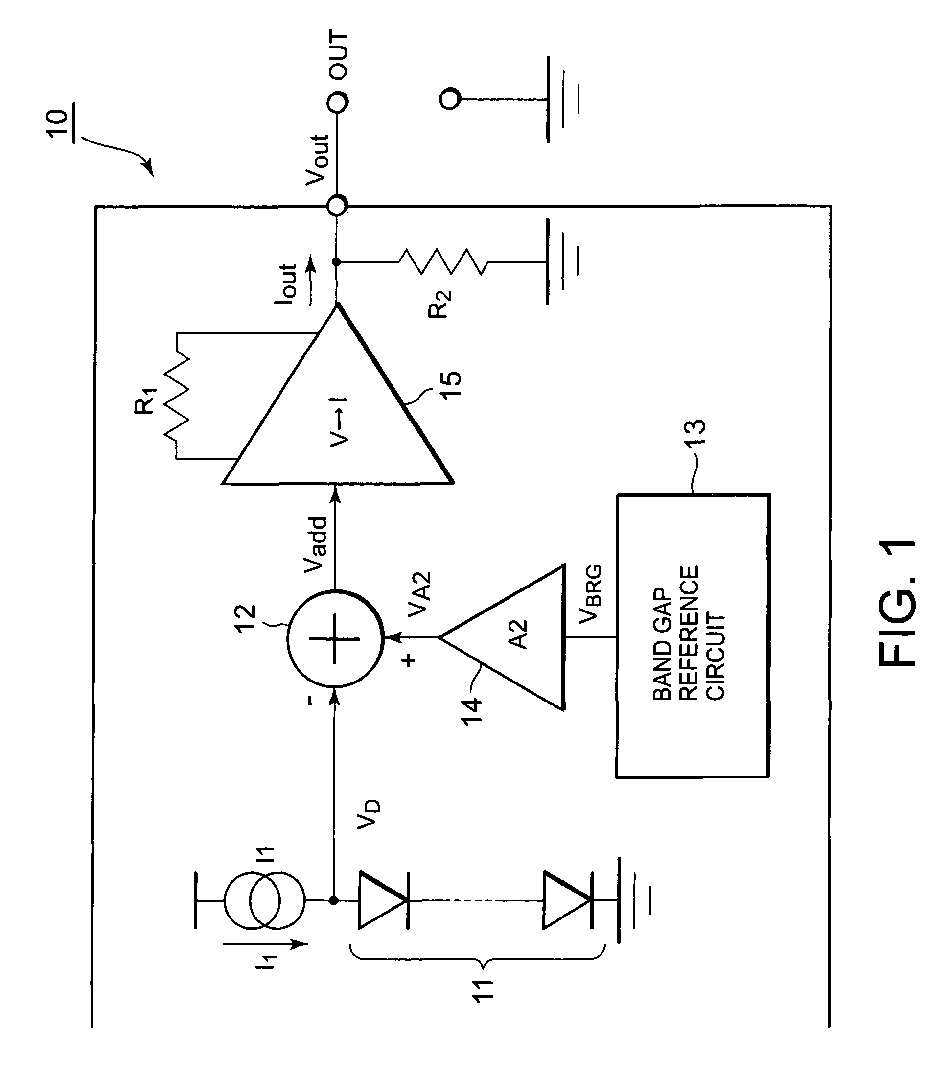
[0060]FIG. 1 is a block diagram showing a temperature detection circuit according to the first embodiment of the present invention. As shown in FIG. 1, a temperature detection circuit 10 comprises a group of diodes 11 consisting of one or more diodes connected in series, a constant current source I1 connected to the group of diodes 11, and an output unit for outputting the voltage or the current according to the detection temperature based on the voltage difference between a comparison voltage and a reference voltage generated by the group of diodes 11.
[0061]The output unit according to the present embodiment is configured by an adder 12, a voltage current converter 15, and a resistor R2 as a second resistor, and outputs a voltage VOUT according to the detection temperature. The temperature detection circuit 10 further comprises a BGR circuit 13 for generating a band gap reference voltage (BGR voltage) and an amplifier 14 for amplifying the BGR voltage, and inputs the voltage having...
second embodiment
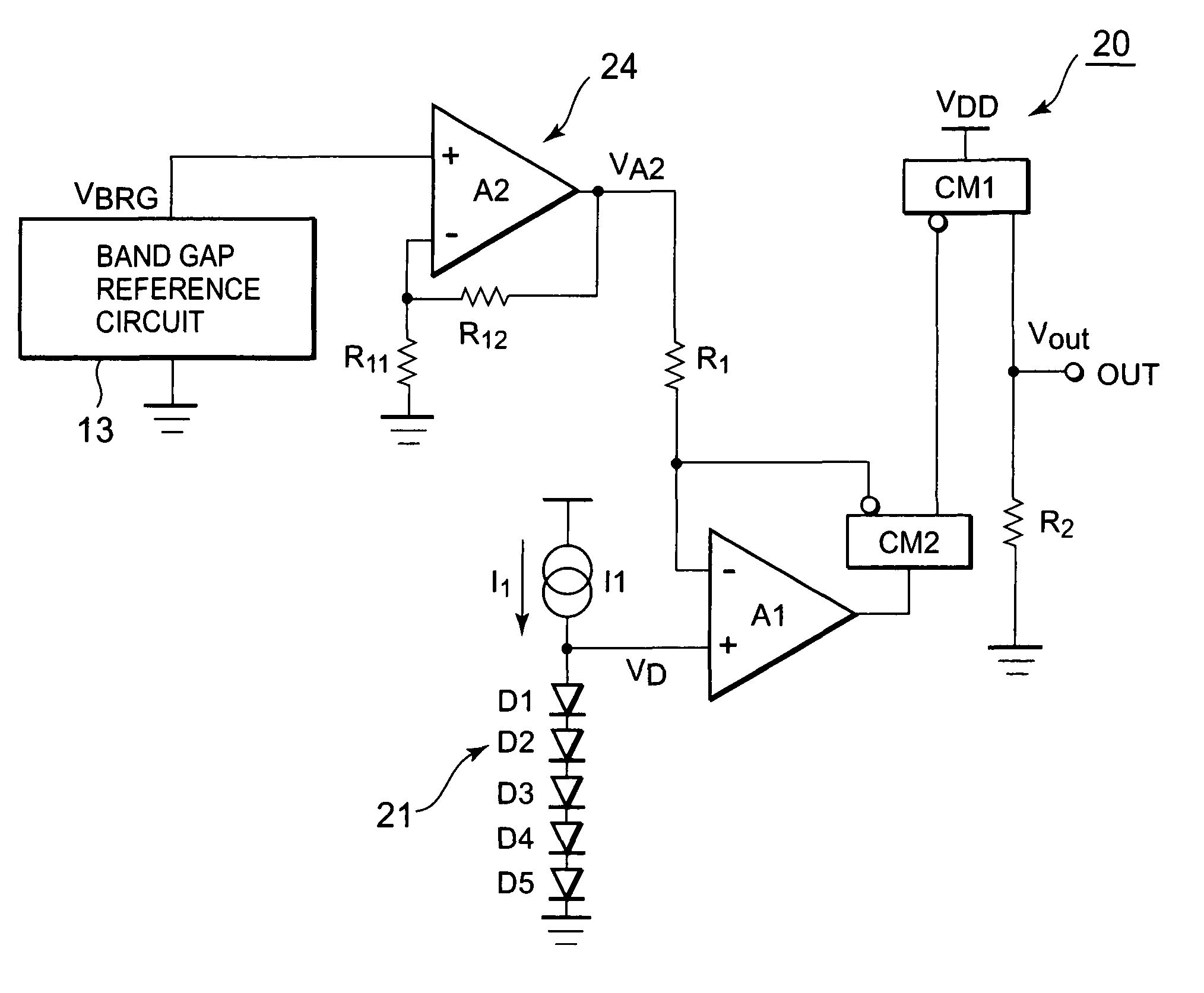
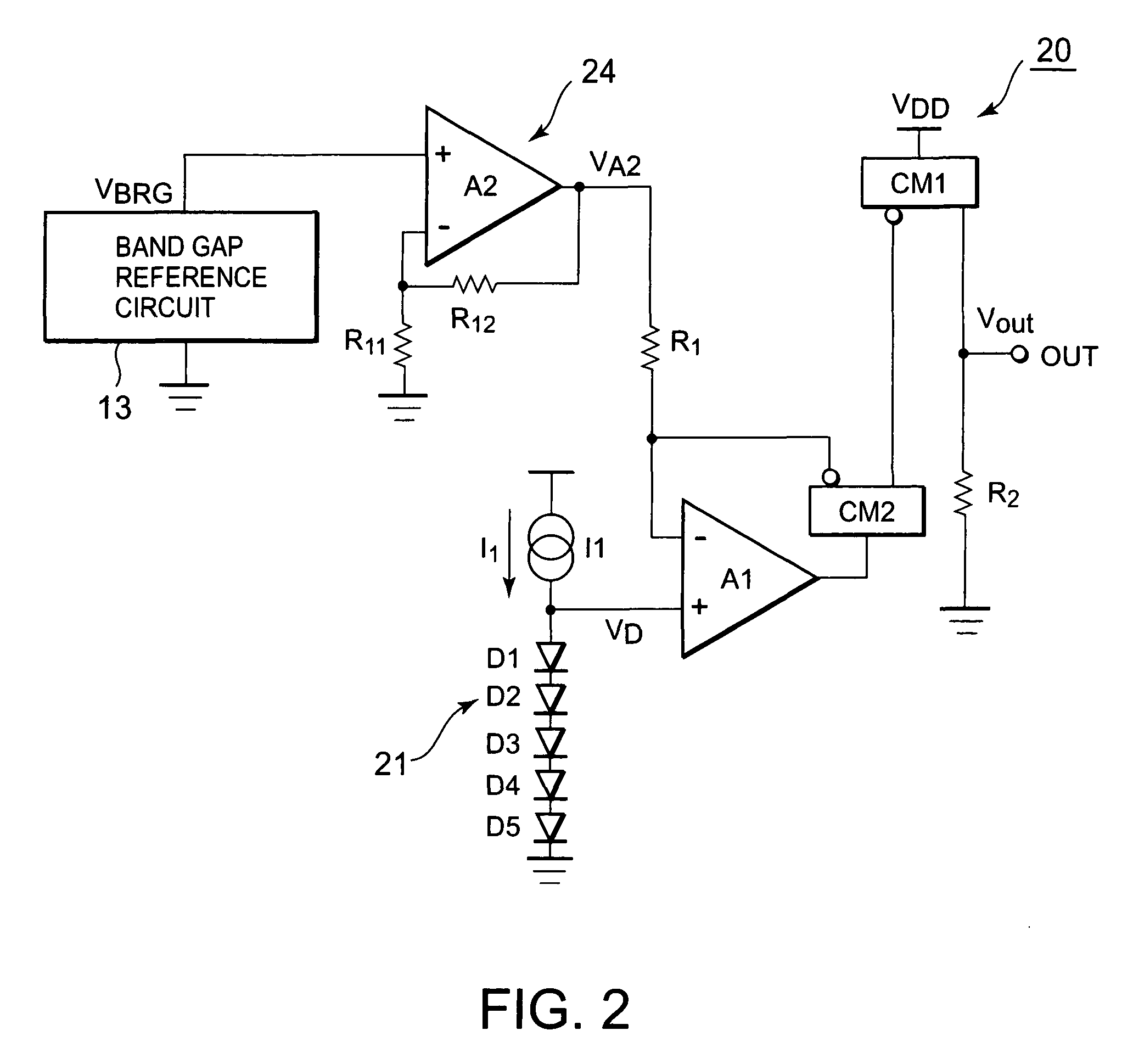
[0091]Next, a second embodiment of the present invention will be described. A temperature detection circuit according to the present invention is such that, when offset voltages of the first and second operational amplifiers A1 and A2 cause a problem, for example, for the temperature detection circuit 20 shown in FIG. 2, measures are taken to meet the problem. FIG. 6 is a view showing a temperature detection circuit according to the present embodiment. Incidentally, in the temperature detection circuit according to the present embodiment shown in FIG. 6, the same component parts as the temperature detection circuit shown in FIG. 2 are attached with the same reference numerals, and the detailed description thereof will be omitted.
[0092]As shown in FIG. 6, a temperature detection circuit 40 according to the present embodiment takes the first and second operational amplifiers A1 and A2 shown in FIG. 2 as operational amplifiers A11 and A12 attached with an offset cancellation circuit, a...
third embodiment
[0112]Next, a third embodiment of the present invention will be described. FIG. 10 is a block diagram showing a temperature detection circuit according to the present embodiment. As shown in FIG. 10, a temperature detection circuit 60 according to the present embodiment is provided with an amplifier 65 in place of the amplifier 14 and the resistor R2 in the temperature detection circuit 10 shown in FIG. 1. Similarly to the first embodiment, the series voltage (comparison voltage) VD of a group of diodes 11 plurally connected in series biased by a constant current source I1 is minus added by an adder 12, and a voltage (reference voltage) VA2 amplifying a BGR voltage VBGR by the amplifier 14 is plus added. The output voltage of this adder 12 is amplified by an amplifier 65, and the amplified voltage is outputted from the output terminal OUT serving as the output terminal of the temperature detection circuit 60.
[0113]Next, the operation of the temperature detection circuit according to...
PUM
| Property | Measurement | Unit |
|---|---|---|
| temperature | aaaaa | aaaaa |
| temperature | aaaaa | aaaaa |
| temperature | aaaaa | aaaaa |
Abstract
Description
Claims
Application Information
 - R&D
- Intellectual Property
- Life Sciences
- Materials
- Tech Scout
- Unparalleled Data Quality
- Higher Quality Content
- 60% Fewer Hallucinations
Browse by: Latest US Patents, China's latest patents, Technical Efficacy Thesaurus, Application Domain, Technology Topic, Popular Technical Reports.
© 2025 PatSnap. All rights reserved.Legal|Privacy policy|Modern Slavery Act Transparency Statement|Sitemap|About US| Contact US: help@patsnap.com


