
Drug delivery systems

a drug delivery and liquid technology, applied in the direction of powder delivery, pharmaceutical delivery mechanism, prosthesis, etc., can solve the problems of low drug level, high initial drug level, and unsuitable or practical conventional drug delivery involving frequent periodic dosing

Inactive Publication Date: 2009-06-09
BAUSCH & LOMB INC
View PDF21 Cites 31 Cited by
  • Summary
  • Abstract
  • Description
  • Claims
  • Application Information

AI Technical Summary

Benefits of technology

Enables controlled and sustained release of pharmaceutically active agents, tailored to the specific drug, location, and therapeutic needs, enhancing treatment efficacy for ophthalmic conditions by maintaining therapeutic drug levels and minimizing side effects.

Problems solved by technology

Conventional drug delivery involving frequent periodic dosing is not ideal or practical in many instances.
For example, with more toxic drugs, conventional periodic dosing can result in high initial drug levels at the time of dosing, followed by low drug levels between doses often times below levels of therapeutic value.
Likewise, conventional periodic dosing may not be practical or therapeutically effective in certain instances such as with pharmaceutical therapies targeting areas of the inner eye or brain in need of treatment such as the retina.
Unfortunately, controlled release drug delivery systems to date do not provide a means by which one may manipulate and control drug delivery systems' drug release rate for specific drugs over a broad range of drugs.

Method used


Image

  • Drug delivery systems
  • Drug delivery systems
  • Drug delivery systems

Examples


example 1

Synthesis of 1,3-bis(4-methacryloyloxybutyl)tetramethyl disiloxane (M2)

[0079]To a four neck resin flask equipped with a mechanical stirrer, Dean-Stark trap, heating mantle, water cooled condenser and thermometer was added 1,1-dimethyl-1-sila-2-oxacyclohexane, methacrylic acid, and concentrated sulfuric acid. To the reaction mixture was then added cyclohexane and hydroquinone as a polymerization inhibitor. The reaction mixture was heated to reflux for five hours during which time of water was collected. The reaction mixture was then cooled, divided, and passed through two chromatography columns filled with alumina (packed using cyclohexane as eluant). The cyclohexane was removed using a rotary evaporator and the resultant M2 is placed under vacuum for one hour at 80° C.

example 2

Synthesis of a methacrylate-terminated siloxane (M2D2)

[0080]To a round bottom flask under dry nitrogen was added D4 (octamethylcyclotetrasiloxane) and the M2 prepared in Example 1. Trifluoromethane sulfonic acid was added as initiator. The reaction mixture was stirred 24 hours with vigorous stirring at room temperature. Sodium bicarbonate is then added and the reaction mixture was again stirred for 24 hours. The resultant solution was filtered through a 0.3μ Teflon® filter. The filtered solution was vacuum stripped and placed under vacuum (>0.1 mm Hg) at 50° C. to remove the unreacted silicone cyclics. The resulting methacrylate terminated siloxane was a viscous, clear fluid.

example 3

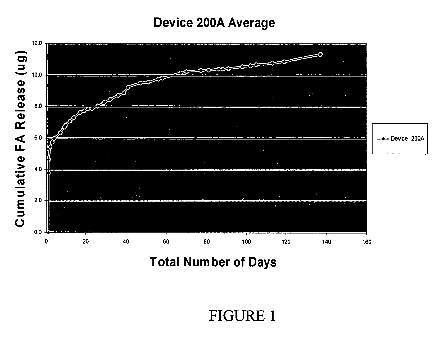
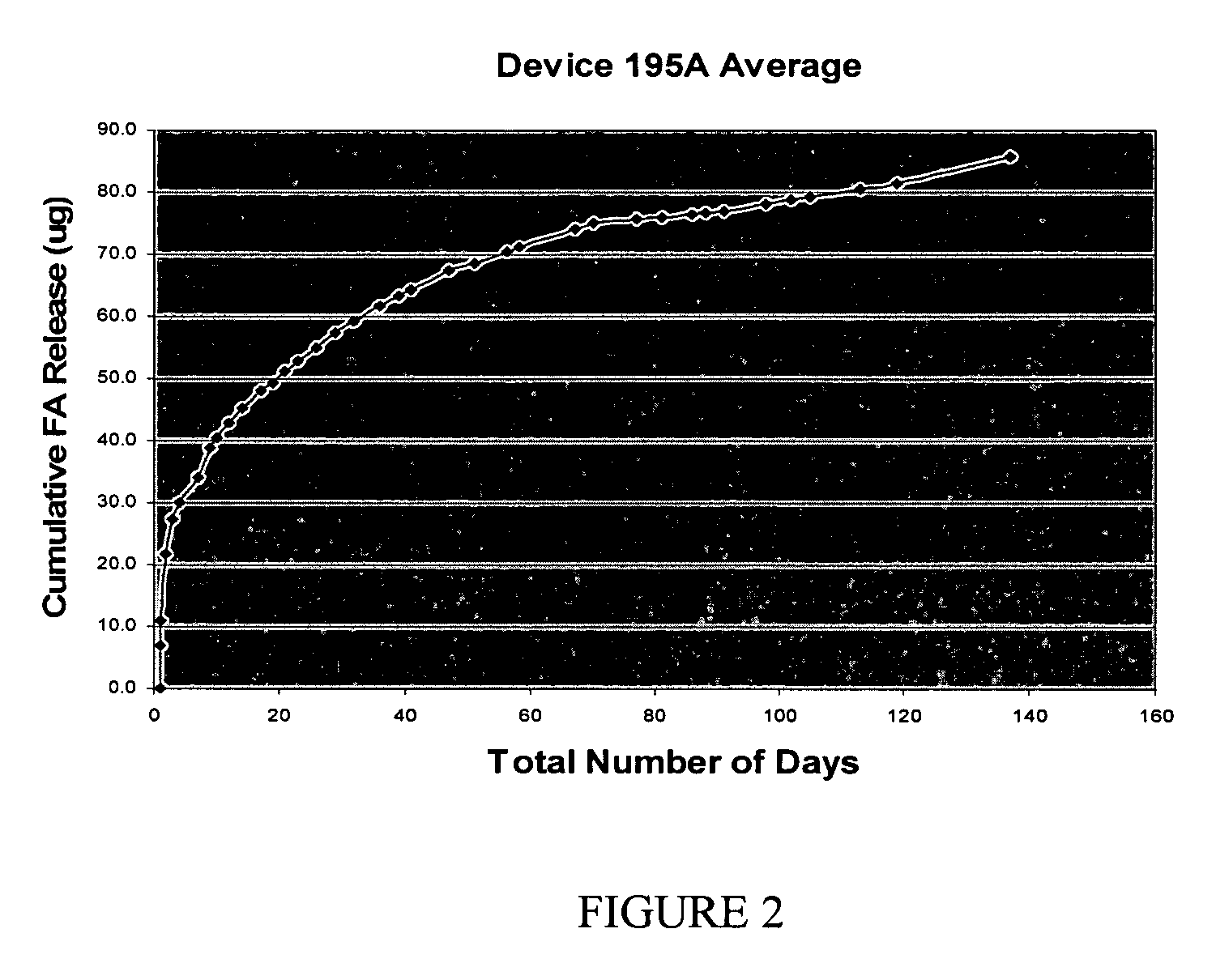
[0081]To 100 parts of the methacrylate terminated siloxane prepared in Example 2 (where x=2) was added 1.0% Irgacure 819 as a photoinitiator and 20% w / w of fluocinolone acetonide (FA). The suspension was added to Teflon tubes (0.5 mm in diameter) available from Boramed (Durham, N.C.) and polymerized using visible light polymerization techniques. The cure conditions consisted of two hours of visible light irradiation. Following the cure the drug loaded copolymer was removed from tube resulting in a release device having dimensions of 5 mm by 0.5 mm.


PUM

PropertyMeasurementUnit
temperatureaaaaaaaaaa
time periodaaaaaaaaaa
lengthaaaaaaaaaa

Abstract

Matrix controlled diffusion drug delivery systems based on one or more silicone-containing monomers of the general formula:wherein x, y, m, m′, R, R1, R2, R3, R4, R5, R6, R7, X, Z and Z′ are as defined herein are provided, wherein the matrix controlled diffusion drug delivery systems are sized and configured for back of the eye delivery.

Description

BACKGROUND OF THE INVENTION[0001]1. Technical Field[0002]The present invention relates generally to hydrogels, drug delivery systems, and methods of treatment.[0003]2. Description of Related Art[0004]Conventional drug delivery involving frequent periodic dosing is not ideal or practical in many instances. For example, with more toxic drugs, conventional periodic dosing can result in high initial drug levels at the time of dosing, followed by low drug levels between doses often times below levels of therapeutic value. Likewise, conventional periodic dosing may not be practical or therapeutically effective in certain instances such as with pharmaceutical therapies targeting areas of the inner eye or brain in need of treatment such as the retina.[0005]During the last two decades, significant advances have been made in the design of controlled release drug delivery systems. See, e.g., U.S. Patent Application Publication Nos. 2004 / 0043067 and 2004 / 0253293. Such advances have been made in...

Claims


Application Information

Patent Timeline
Patent Type & Authority Patents(United States)
IPC IPC(8): A61K9/14A61F2/00
CPCA61K9/0048A61K47/34
Inventor KUNZLER, JAYSALAMONE, JOSEPH
Owner BAUSCH & LOMB INC
Learn More