
Lithographic and measurement techniques using the optical properties of biaxial crystals

a technology of optical properties and biaxial crystals, applied in the field of lithography, microscopy and overlay methods, can solve the problems of limiting the measurable volume, not having modern technology applications, and relatively small number of generic effects available, and achieve the effect of accurately retrieving the position of optical features

Inactive Publication Date: 2009-06-02
RGT UNIV OF CALIFORNIA
View PDF1 Cites 18 Cited by
  • Summary
  • Abstract
  • Description
  • Claims
  • Application Information

AI Technical Summary

Benefits of technology

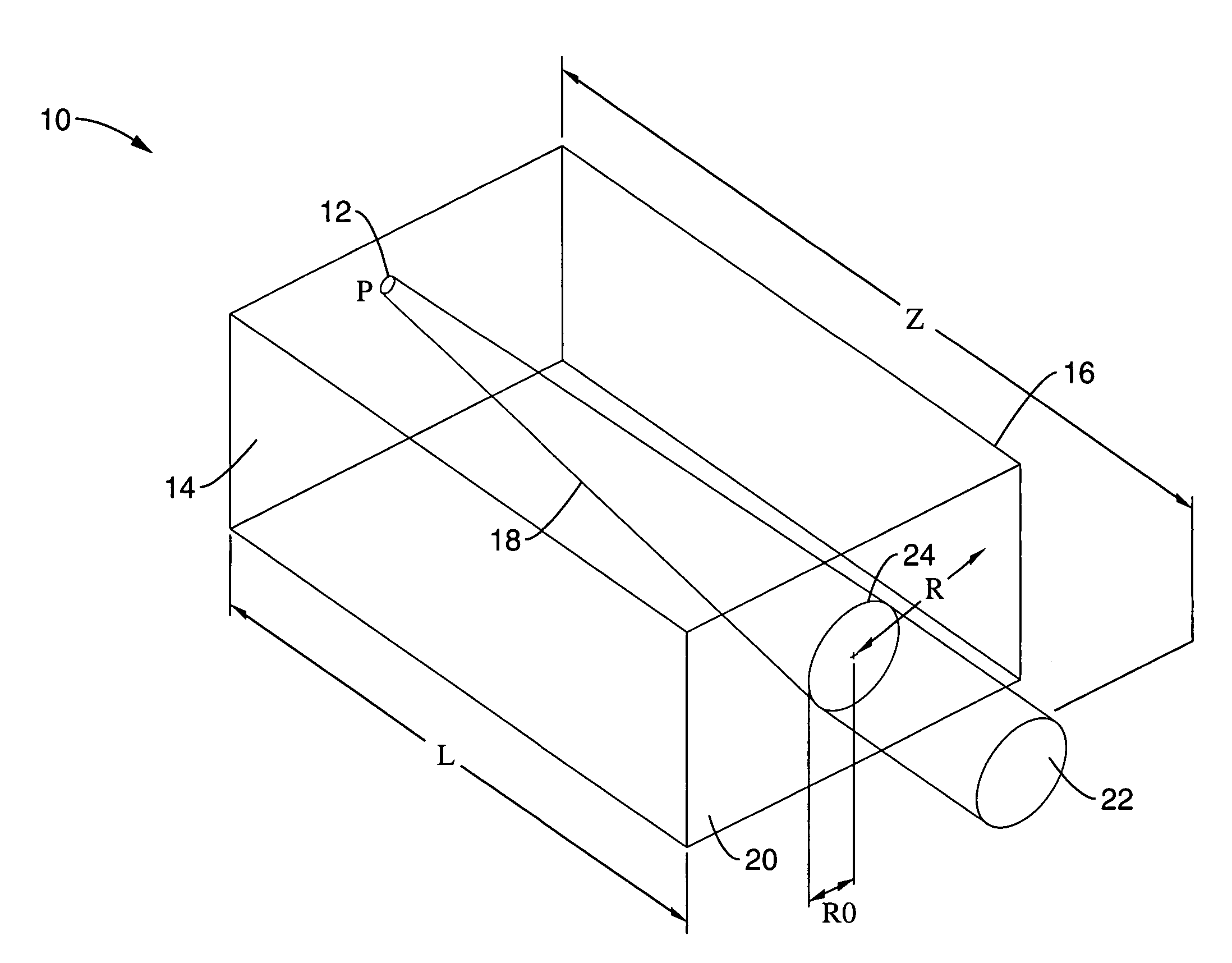
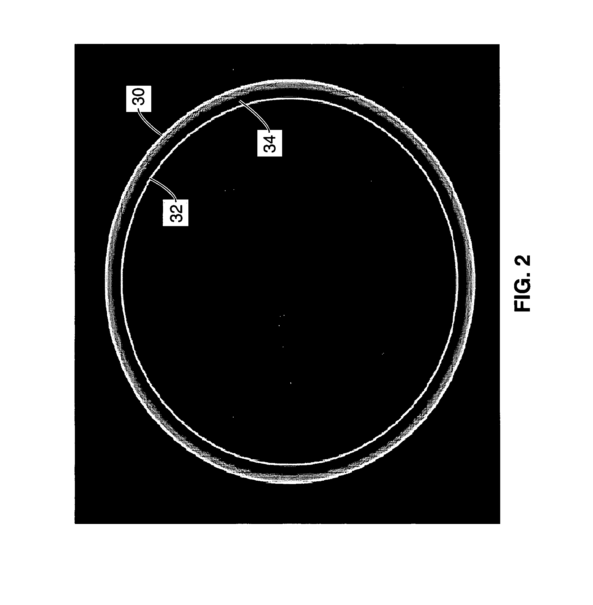
[0028]The present invention is a method for accurately retrieving the position of an optical feature. The method uses the optical properties of biaxial crystals to filter optically an image and to spatially discriminate and position small features.
[0029]Existing methods rely on regular linear optics. In contrast, however, the present invention is based on singular optics. In practice, this implies that a beam of light is converted to a thin cone, which will be easy to image.

Problems solved by technology

However, despite the broad array of applications, only a relatively small number of generic effects are available.
However, it does not have applications in modern technologies, as only recently suitable crystals with large conical effects have been developed (Berry, M. V., Conical diffraction asymptotics: fine structure of Poggendorff rings and axial spike.
However, diffraction limits and the lack of field depth restrict the measurable volume.
Overlay metrology is a major challenge in Lithography, for any lithographic technique.
These marks have been evaluated by manufacturers, selected users, NIST and SEMATECH, and the conclusion is that the main source of uncertainty in the newest technologies is the unmodeled residuals of the process.

Method used


Image

  • Lithographic and measurement techniques using the optical properties of biaxial crystals
  • Lithographic and measurement techniques using the optical properties of biaxial crystals
  • Lithographic and measurement techniques using the optical properties of biaxial crystals

Examples


Embodiment Construction

[0076]Referring more specifically to the drawings, for illustrative purposes the present invention is embodied in the apparatus generally shown in FIG. 1 through FIG. 17. It will be appreciated that the apparatus may vary as to configuration and as to details of the parts, and that the method may vary as to the specific steps and sequence, without departing from the basic concepts as disclosed herein.

[0077]The present invention generally involves a method in which the image of a light point is represented by a circle by using the properties of propagation of light in biaxial crystals close to the optical axis. Theoretically, optical propagation in biaxial crystals is specific due to the existence of a conical singularity (internal conical refraction) and a toroidal ring (external conical refraction) of the dispersion surface, as described in Berry, M. V., previously incorporated by reference. This specificity creates a behavior of the light propagation different from those obtained ...


PUM

PropertyMeasurementUnit
radiusaaaaaaaaaa
frequencyaaaaaaaaaa
optical featureaaaaaaaaaa

Abstract

A method and apparatus for accurately retrieving the position of an optical feature. The method uses the optical properties of biaxial crystals to conically refract the optical feature and transform the image of the optical feature to a circular ring structure. The position of the optical feature is then calculated by locating a center point associated with the circular ring structure.

Description

CROSS-REFERENCE TO RELATED APPLICATIONS[0001]This application claims priority from U.S. provisional application Ser. No. 60 / 728,448, filed on Oct. 19, 2005, incorporated herein by reference in its entirety, and U.S. provisional application Ser. No. 60 / 700,017, filed on Jul. 15, 2005, incorporated herein by reference in its entirety.STATEMENT REGARDING FEDERALLY SPONSORED RESEARCH OR DEVELOPMENT[0002]Not ApplicableINCORPORATION-BY-REFERENCE OF MATERIAL SUBMITTED ON A COMPACT DISC[0003]Not ApplicableNOTICE OF MATERIAL SUBJECT TO COPYRIGHT PROTECTION[0004]A portion of the material in this patent document is subject to copyright protection under the copyright laws of the United States and of other countries. The owner of the copyright rights has no objection to the facsimile reproduction by anyone of the patent document or the patent disclosure, as it appears in the United States Patent and Trademark Office publicly available file or records, but otherwise reserves all copyright rights ...

Claims


Application Information

Patent Timeline
Patent Type & Authority Patents(United States)
IPC IPC(8): G01J1/00G01N21/00G01N23/00
CPCG02B1/02G03F7/70633G03F7/70966
Inventor NEUHAUSER, DANIELSIRAT, GABRIEL Y.
Owner RGT UNIV OF CALIFORNIA
Learn More