
Method and apparatus for controlling thermal stress in lighting devices

a technology for lighting devices and thermal stress, applied in the field of lighting, can solve the problems of unsuitable alternating currents, unsuitable leds, and insufficient protection of leds from thermal stress, and achieve the effect of reducing the thermal stress in lighting components

Active Publication Date: 2009-05-26
SIGNIFY HLDG BV
View PDF31 Cites 145 Cited by
  • Summary
  • Abstract
  • Description
  • Claims
  • Application Information

AI Technical Summary

Benefits of technology

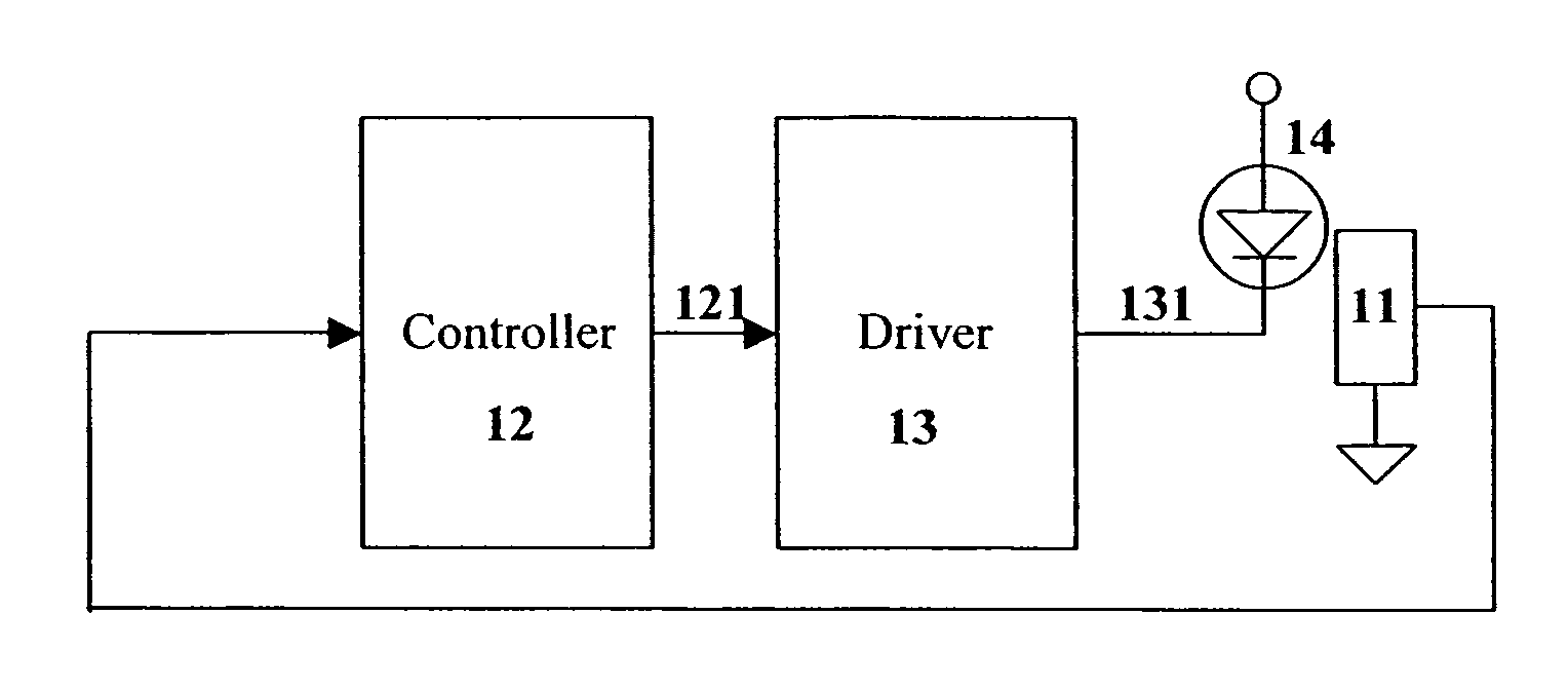
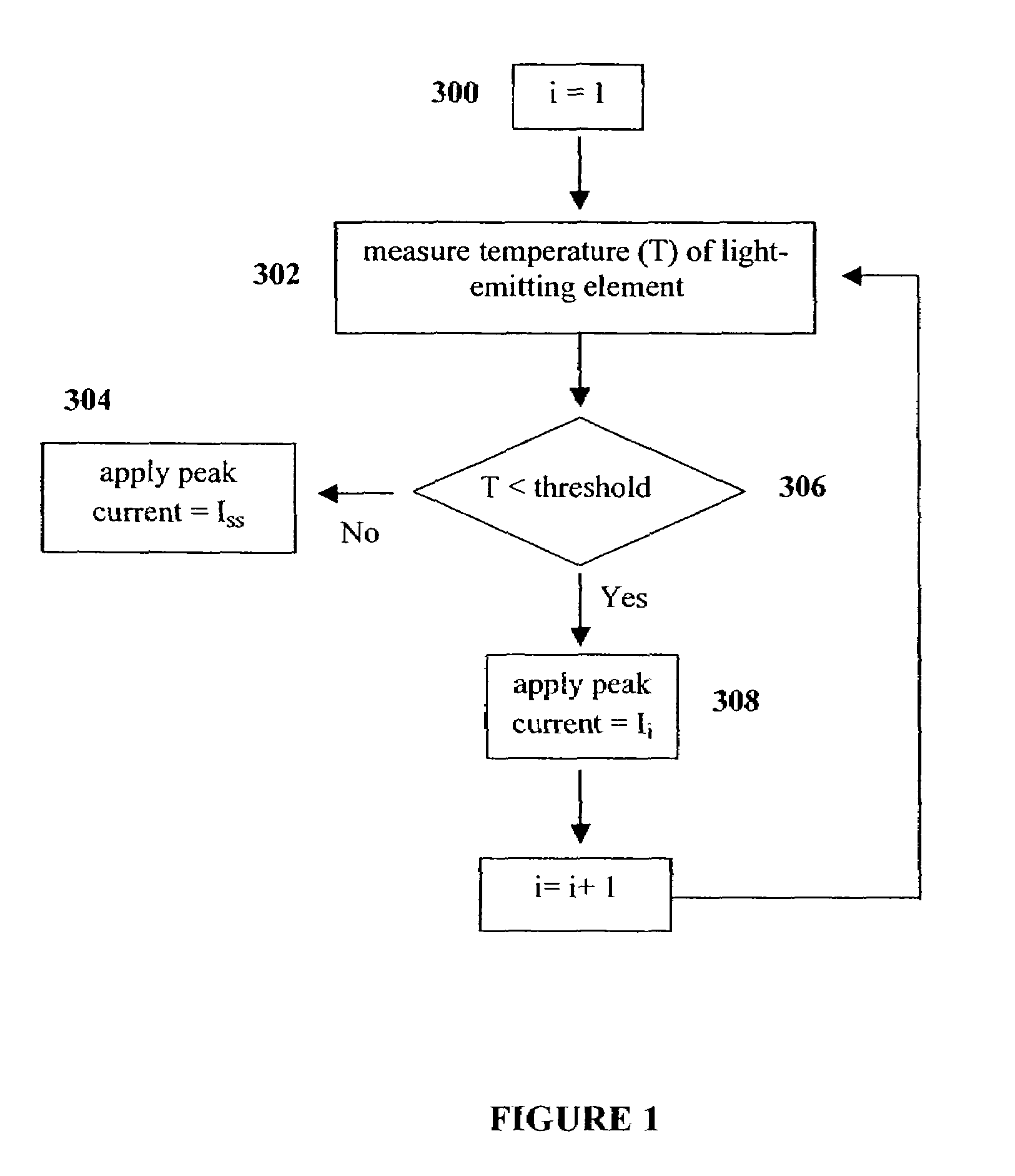
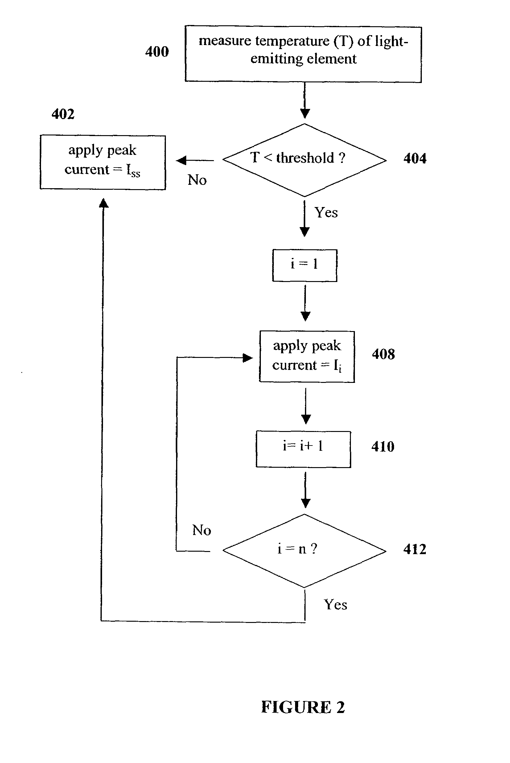
The present invention provides a method and apparatus for controlling thermal stress in lighting components, such as LEDs, that can be exposed to relatively large thermal gradients. The apparatus includes a temperature determination means and a control means. The temperature determination means detects the initial temperature of the lighting elements and sends the data to the control means. The control means then determines an initial drive signal based on the temperature data and ramps it up to a steady state drive signal based on predetermined criteria. This helps to reduce the thermal stresses in the lighting components and improves their performance and reliability.

Problems solved by technology

The thermal stresses due to rapidly heating and cooling of components within lighting systems can lead to a number of failures such as the fracture of wire bonds and lift off of a LED die from the package.
The invention however, only works with alternating currents which are not suitable for LEDs since they are typically operated with direct currents.
U.S. Pat. No. 6,573,674 also discloses a circuit for controlling a load supplied with an alternating current and is similarly unsuitable for LEDs.
The invention however, does not protect the LEDs from thermal stress resulting from storage at low ambient temperatures for example.
This method of maintaining the junction temperature of an LED can be inappropriate for some LEDs as the reverse breakdown voltage of the LED may need to be exceeded in order to achieve the desired result.
This method of suppressing thermal effects however, results in additional power consumption in order to maintain the temperature of the LEDs at a desired level, which may be relatively large when LEDs are being used in an outdoor environment, for example.
In both of these disclosures however, the rate at which a signal is provided to a load is predetermined and may not sufficiently reduce thermal stresses in cold environments, for example.

Method used


Image

  • Method and apparatus for controlling thermal stress in lighting devices
  • Method and apparatus for controlling thermal stress in lighting devices
  • Method and apparatus for controlling thermal stress in lighting devices

Examples


Embodiment Construction

Definitions

[0023]The term “light-emitting element” is used to define any device that emits radiation in any region or combination of regions of the electromagnetic spectrum for example, the visible region, infrared and / or ultraviolet region, when activated by applying a potential difference across it or passing a current through it, for example. Therefore a light-emitting element can have monochromatic, quasi-monochromatic, polychromatic or broadband spectral emission characteristics. Examples of light-emitting elements include semiconductor, organic, or polymer / polymeric light-emitting diodes, optically pumped phosphor coated light-emitting diodes, optically pumped nano-crystal light-emitting diodes or any other similar light-emitting devices as would be readily understood by a worker skilled in the art. Furthermore, the term light-emitting element is used to define the specific device that emits the radiation, for example a LED die, and can equally be used to define a combination ...


PUM


Abstract

The present invention provides a method and apparatus for controlling the thermal stress in lighting devices, for example light-emitting elements, that are exposed to large thermal gradients typically upon start-up, for example light-emitting elements operating in relatively cold ambient environments. The present invention provides an apparatus that can reduce this thermal stress, wherein the apparatus comprises a temperature determination mechanism for evaluating the temperature of the light-emitting elements prior to activation, and a control system to control the drive current such that it is gradually ramped up to the desired steady state peak current value, wherein the ramping of the drive current is dependent on the evaluated temperature of the light-emitting element.

Description

[0001]The present application claims the benefit of U.S. Provisional Application No. 60 / 658,857, which was filed on Mar. 3, 2005, and is incorporated by reference herein.FIELD OF THE INVENTION[0002]The present invention pertains to the field of lighting and in particular to a method and apparatus for controlling thermal stress in lighting devices.BACKGROUND[0003]Recent advances in the development of solid-state light-emitting devices such as light-emitting diodes (LEDs) including semiconductor LEDs, small molecule organic light-emitting diodes (OLEDs) and polymer light-emitting diodes (PLEDs), have made these devices suitable for use in general illumination applications, including architectural, entertainment, and roadway lighting, for example. As such, LEDs are becoming increasingly competitive with light sources such as incandescent, fluorescent, and high-intensity discharge lamps.[0004]LEDs offer a number of advantages and are generally chosen for their ruggedness, long lifetime,...

Claims


Application Information

Patent Timeline
Patent Type & Authority Patents(United States)
IPC IPC(8): H05B37/02H05B44/00
CPCH05B33/0803H05B33/0854H05B45/18
Inventor ASHDOWN, IAN
Owner SIGNIFY HLDG BV
Learn More