Eureka AIR delivers breakthrough ideas for toughest innovation challenges, trusted by R&D personnel around the world.

Process for high shear gas-liquid reactions

a gas-liquid reaction and high shear technology, applied in chemical/physical/physical-chemical processes, chemical/physical/physical-chemical stationary reactors, energy-based chemical/physical/physical-chemical processes, etc., can solve the problems of affecting the overall efficiency of the process, unable to provide adequate interfacial contact area between liquid and gas, and unfavorable gas-liquid reaction results. , the effect of improving the reaction rate and improving the reaction ra

Inactive Publication Date: 2009-05-26
323 TRUST +1
View PDF111 Cites 34 Cited by
  • Summary
  • Abstract
  • Description
  • Claims
  • Application Information

AI Technical Summary

Benefits of technology

[0026]Accordingly, a method and apparatus are disclosed, the method and apparatus for producing a gas-in-liquid emulsion for providing increased interfacial contact area between the liquid and the gas for improved reaction of the gas with the liquid, or more rapid solution or reaction of a difficulty soluble or immiscible gas in or with a liquid.
[0027]The method provides a superior, more economical and more efficient way of contacting gases with liquids for the purpose of effecting reactions between them to be carried out as a continuous or batch type process.

Problems solved by technology

However, this gas / liquid reaction method provides a relatively small gas / liquid contact area and is prone to considerable back-mixing (mixing in the longitudinal, axial or general flow direction) of the gas component thus providing an undesirably large residence time distribution (RTD), impairing the overall efficiency of the process.
Sparging gasses through liquids for reacting the gasses with the liquids is also known in the prior art, but also fails to provide adequate interfacial contact area between the liquid and gas.

Method used


Image

  • Process for high shear gas-liquid reactions
  • Process for high shear gas-liquid reactions
  • Process for high shear gas-liquid reactions

Examples


Embodiment Construction

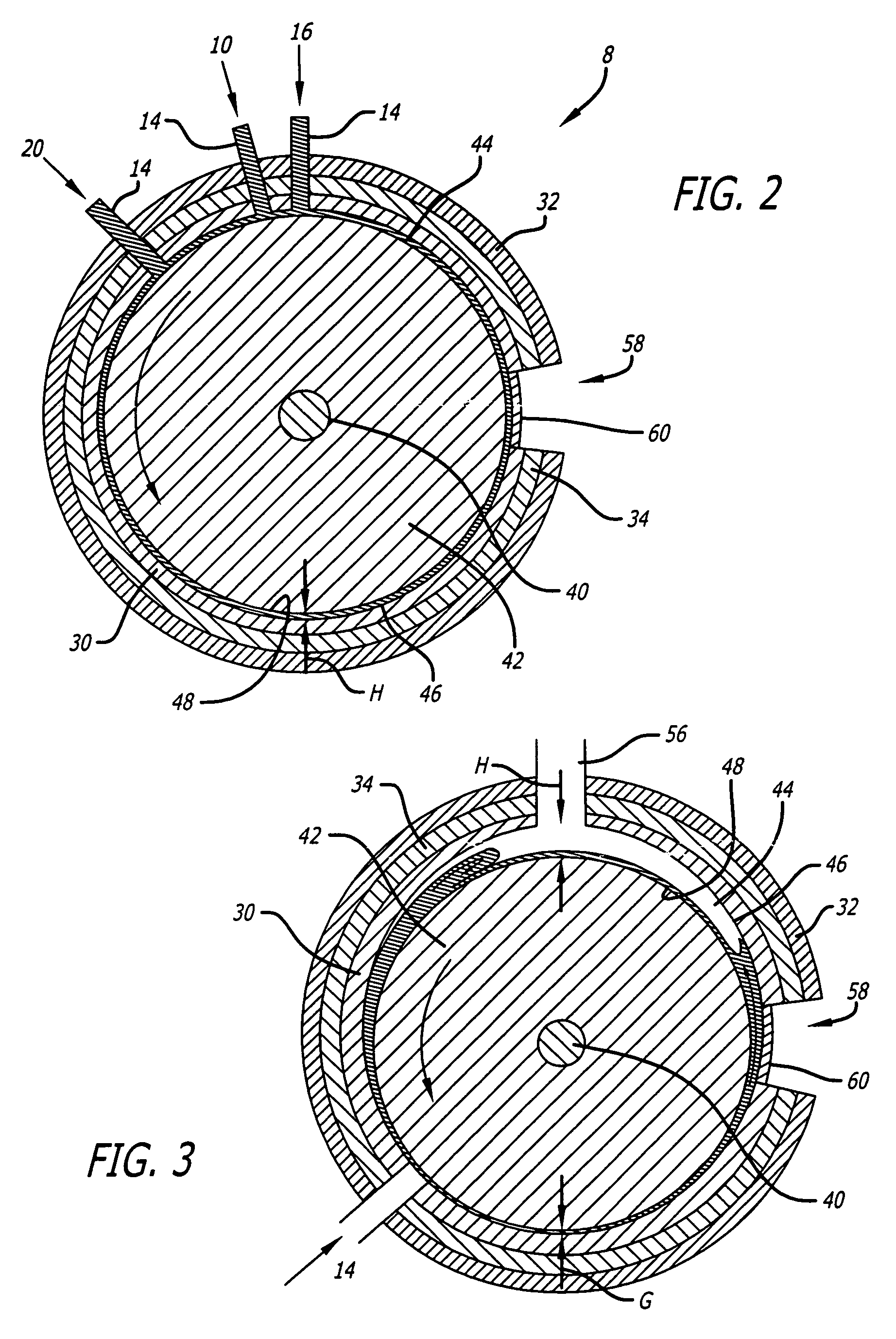
[0034]An efficient reaction process is herein disclosed between reactants, wherein the reactants and a catalyst may be in different states, such as gas, liquid and solid. Accordingly, two or more reactants can be reacted in presence of a catalyst in a 3-phase system, wherein at least one first reactant is in a liquid phase, and at least one second reactant is in a gas phase, while the catalyst can be in a solid phase, such as a powder or a paste.

[0035]The first reactant and the second reactant can be preheated to a predetermined reaction temperature, while the catalyst may or may not be preheated. In the reactions discussed below, the catalyst is preferably not preheated. Therefore, depending on the parameters, pre-heating of any of the components may or may not be necessary. In addition to other parameters, the temperature can be controlled to optimize the reactions.

[0036]The first reactant and second reactant are introduced into the system in a passage defined by a first and a sec...


PUM

PropertyMeasurementUnit
speedaaaaaaaaaa
temperatureaaaaaaaaaa
flow rateaaaaaaaaaa

Abstract

A process for performing a chemical reaction between a plurality of chemical reactants in the presence of a catalyst, with at least a first reactant in a liquid phase and at least a second reactant in a gas phase, the first and second reactants mixing at least by interdiffusion. The process comprises supplying the reactants to a passage defined by a first surface and a second surface and optionally moving at least one of the first surface and second surface relative to each other. The reactants their mixture or reaction products form respective boundary layers against the first and second surfaces and the radial spacing between the first surface and second surface is equal to or less than the back-to-back radial thicknesses of the boundary layers.

Description

CROSS REFERENCE TO RELATED APPLICATIONS[0001]This application is a continuation-in-part of U.S. application Ser. No. 09 / 894,996, filed Jun. 27, 2001, now U.S. Pat. No. 6,742,774 which is a continuation-in-part of U.S. application Ser. No. 09 / 853,448, filed on May 10, 2001, now U.S. Pat. No. 6,723,999, and a continuation-in-part of U.S. application Ser. No. 09 / 802,037, filed on Mar. 7, 2001, now U.S. Pat. No. 6,471,392, and a continuation-in-part of U.S. application Ser. No. 09 / 345,813, filed on Jul. 2, 1999, now U.S. Pat. No. 6,391,082, and which claims the benefit of the prior filing date of U.S. Provisional Application No. 60 / 214,538, filed Jun. 27, 2000, and also of U.S. Provisional application Ser. No. 10 / 661,170 filed Sep. 11, 2003, which claims the benefit of the prior filing date of U.S. provisional patent application No. 60 / 410,185, filed Sep. 11, 2002, herein incorporated by reference in their entirety.BACKGROUND OF THE DISCLOSURE[0002]1. Field of the Disclosure[0003]The pr...

Claims


Application Information

Patent Timeline
Patent Type & Authority Patents(United States)
IPC IPC(8): C07C51/36C07C51/255B01F27/74B01J19/08B01J19/10B01J19/12B01J19/18B29B7/40B29B7/90B29C48/38C02F1/30C02F1/32C02F1/36C08K3/00F28D11/02H05K1/03H05K3/02
CPCB01F7/008B01F7/12B01F13/0001B01F15/00714B01J19/082B01J19/10B01J19/122B01J19/125B01J19/126B01J19/127B01J19/18B01J19/1887B29B7/401B29B7/90B29C47/50C08K3/0008F28D11/02B01F7/005B01F15/00844B01F15/00909B01F15/06B01F2013/1086B01F2013/1091B01J2208/00B01J2219/00094B01J2219/00141B01J2219/00146B01J2219/00164B01J2219/00166B01J2219/00168B01J2219/0888B01J2219/1227B01J2219/182B01J2219/1943B22F2998/00B29C47/0009B29K2021/00B29K2105/16B29K2503/04C02F1/30C02F1/302C02F1/32C02F1/36C22C32/0094C08K3/01B29C48/03B29C48/38B29B7/603B29B7/826B29B7/385B01F27/116B01F27/272B01F27/74B01F33/05B01F33/8362B01F33/83613B01F35/4122B01F35/512B01F35/54B01F35/90
Inventor HOLL, RICHARD A.GULLIVER, ERIC A.CIHONSKI, JOHN L.
Owner 323 TRUST
Why Eureka
Eureka Blog
Learn More