
Method for constructing patterns in a layered manner

a technology of layered construction and pattern, applied in the field of layered construction of patterns, can solve the problems of high risk of breakage, superfluous application of binding agent, and considerable disadvantages in production processes

Active Publication Date: 2009-05-12
EXONE
View PDF179 Cites 109 Cited by
  • Summary
  • Abstract
  • Description
  • Claims
  • Application Information

AI Technical Summary

Benefits of technology

The present invention is a process to create models by layering materials on a platform. The process involves applying a first material in layers, followed by selectively adding a second material in layers. This process is repeated until the desired pattern is achieved. The two materials can form a solid if a suitable mixture ratio is used, and the first material is a mixture of materials. The material mixture is prepared before each application stage. The technical effect of this invention is the ability to create complex models with precise accuracy using a simple process involving layered materials.

Problems solved by technology

This requires a threefold application of materials for every layer and is therefore very time-consuming.
This means that only the particulate material containing resin must be applied and the application of the binding agent is superfluous.
However, this production process also has considerable disadvantages.
Apart from the additional process step in the oven there is a high risk of breakage while de-sanding and handling the “green parts”.
During the oven process an undesired distortion of the components can also occur.
Furthermore croning sands have a relatively high thermic stability, which leads to a poor de-coring capability at the relatively low casting temperatures associated with light alloy casting.
The consequence of this are larger quantities of gas during the pyrolysis of the binder while casting and therefore a higher reject risk due to blowholes in the component.
Moreover selective laser sintering in general has the disadvantage that the laser is a complex technique and in addition the exposure phase is also relatively time-consuming.
Furthermore only a very limited choice of sand types and grain sizes are available for selective laser sintering, which means that this process is also not very flexible.
It must be said that, because of the unfavourable material properties, typical traditional foundry binders can be administered only with great technical effort.
There is also a danger that the nozzles used to measure out the binding agent become clogged and unusable.
Using a drop dispenser to administer the binding agent makes the mixing of the binder in the component very poor.
In order to reach comparable rigidities as with conventionally mixed sands, much higher quantities of binder must be added, which again leads to problems in casting because of the higher quantities of gas.
However, gas curing is very elaborate for this process.
Materials which create a health hazard such as SO2 are partly necessary, meaning that a very large amount of equipment is required and the safe operation of the apparatus becomes very costly.
As prior to the curing process not even the slightest solidification of the component takes place, slight displacement of the powder bed while layering can lead to the destruction of the entire component.
However, curing of the components is very complex in this process too, because the necessary narrow tolerance in the change of temperature requires an extensive use of equipment.
The disadvantages of this process include the complex spray application of the binder, inhomogeneous binder mixing and the high concentration of binder in the component.
Moreover, due to the formation of mist in the building chamber caused by the spraying process, a high degree of soiling of the apparatus is consequently caused.
As a result an elaborate cleaning of the print head is necessary, as otherwise a hardening of the material on the nozzles occurs and causes its destruction.

Method used


Image

  • Method for constructing patterns in a layered manner
  • Method for constructing patterns in a layered manner
  • Method for constructing patterns in a layered manner

Examples


Embodiment Construction

[0028]Given this background situation, it is the task of the invention as set out here to make available a process whereby it is possible to carry out layer-by-layer configuration of patterns in the most time-saving and cost-effective manner. Furthermore the process should be able to be used industrially based on its reliability and user-friendliness.

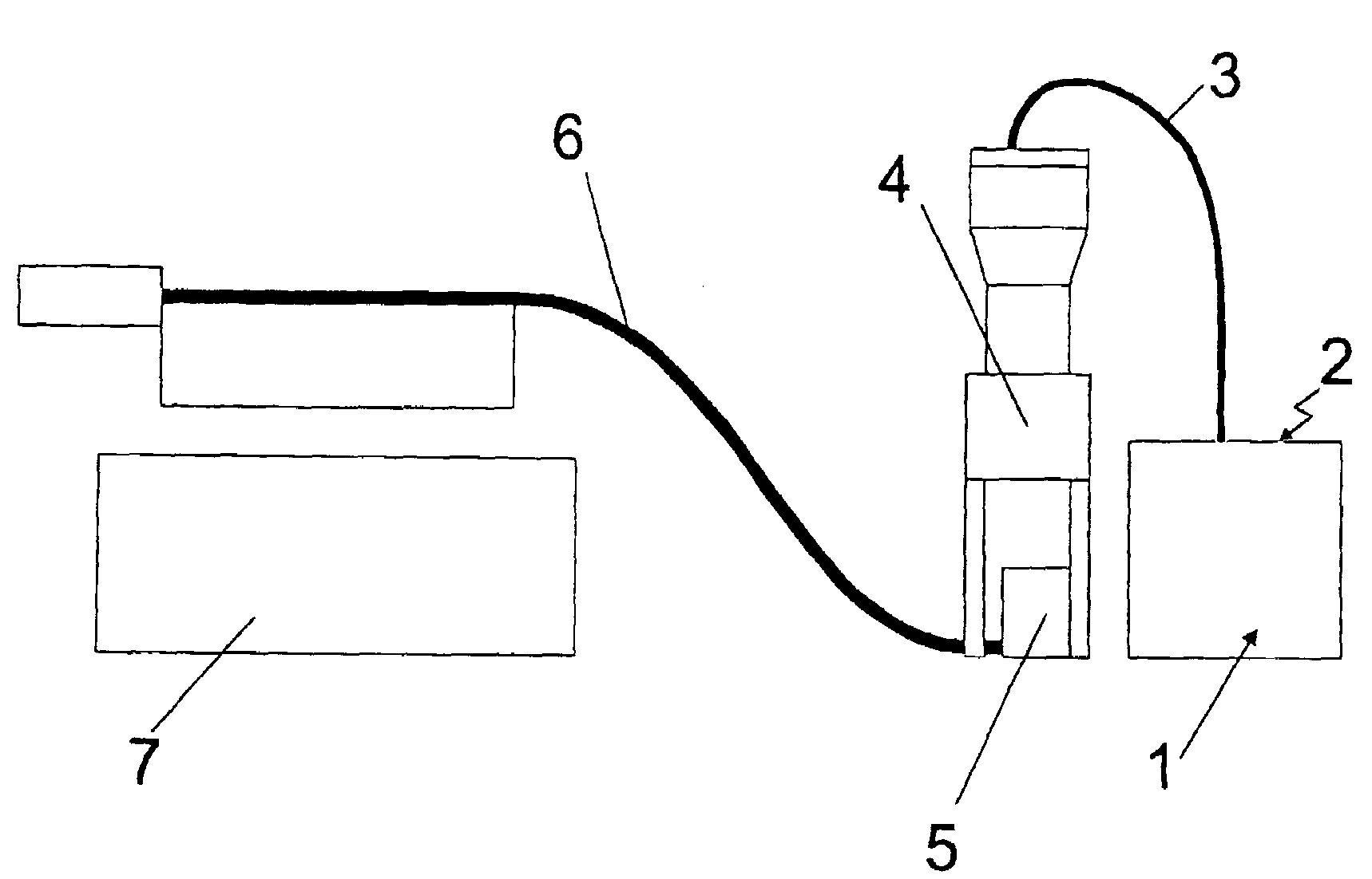
[0029]This task is solved by implementing a process for the configuration of patterns in layers, whereby using a building platform, a first material and then selectively a second material are each applied in layers and these two application steps are continually repeated until a desired pattern is achieved. To this end, the two materials form a solid, provided a suitable mixture ratio is used. The first material concerned is a material mix and is at least partially prepared prior to each layer stage.

[0030]This process has proved itself to be advantageous, as it means that the processing times of the material mixture can be kept short an...


PUM


Abstract

A process to produce models in layers is described, whereby a first material and then selectively a second material is applied in layers on a building platform and these two application stages are repeated until a desired pattern is achieved. The two materials form a solid if a suitable mixture ratio is used and the first material is a material mixture. The material mixture is at least partially prepared prior to each application stage.

Description

CLAIM OF PRIORITY[0001]The present application claims the benefit of the filing date of internation Application Serial No. PCT / DE03 / 01636, filed May 20, 2003 (published as WO03 / 103932, which in turn claims the benefits of German application DE10224981.4, filed Jun. 5, 2002, the contents of which are hereby incorporated by reference in their entirety.TECHNICAL FIELD[0002]The invention as described here refers to a process of layer-by-layer configuration of patterns and / or moulds.BACKGROUND[0003]The application of the rapid prototyping process is well-known as state-of-the-art technology in the production of casting moulds or casting patterns without the use of tools.[0004]A rapid prototyping process to configure casting patterns in particular is already familiar from DE 198 53 834 A1, for example. In this process untreated particulate material, such as quartz sand, is applied on a building platform in a thin layer. Then with the aid of a spray appliance a binding agent is sprayed ont...

Claims


Application Information

Patent Timeline
Patent Type & Authority Patents(United States)
IPC IPC(8): B29C67/00B29C67/24
CPCB29C67/0081B29C67/246B29K2105/16B22C9/10B22C23/00B29C64/165B33Y10/00Y02P10/25B33Y70/10
Inventor EDERER, INGOHOCHSMANN, RAINER
Owner EXONE
Learn More