
Apparatus and method for instruction-level specification of floating point format

a floating point and instruction-level technology, applied in the field of microelectronics, can solve the problems of scarce means whereby the use of these features is enabled, the lack of “spare” instructions in certain cases, and the inability to specify floating point formats

Inactive Publication Date: 2009-05-05
VIA TECH INC
View PDF56 Cites 21 Cited by
  • Summary
  • Abstract
  • Description
  • Claims
  • Application Information

AI Technical Summary

Benefits of technology

This solution allows for efficient specification of floating point formats within microprocessor instructions, improving performance by eliminating the need for slow register updates and maintaining legacy compatibility, thus supporting modern programming needs.

Problems solved by technology

Quite frankly, a present day microprocessor is an amazingly complex and capable machine in comparison to its 30-year-old predecessors.
Yet while in the past developers have been able to incorporate newly developed architectural features into existing instruction set architectures, the means whereby use of these features is enabled—programmable instructions—have become scarce.
More specifically, there are no “spare” instructions in certain instruction sets of interest that provide designers with a way to incorporate newer features into an existing architecture.
But, as one skilled in the art will appreciate, present day microprocessor architectures do not provide for such specification.
This particular floating point format as specified within a given floating point control word may indeed suffice for some floating point algorithms, but it is entirely insufficient for other algorithms which may require a different precision or rounding mode.
Moreover, one skilled will appreciate that although a typical instruction set architecture will provide an instruction (e.g., FLDCW) that directs a microprocessor to load a new floating point control word from memory in order to change the floating point format, the execution speed of this instruction is excruciatingly slow.
It follows then that the performance of such an operation results in a serious performance bottleneck—even in the presence of a single floating point format change.
And, as one skilled in the art will appreciate, although writing a floating point result out to memory and then reading it back into a floating point unit is not as slow as executing an instruction to load a new floating point control word, such an approach still results in a performance bottleneck.
Yet, although these needs have been noted, many instruction set architectures (including the current x86 instruction set architecture) have no means available to provide the desired features without sacrificing operability of some currently used opcodes.

Method used


Image

  • Apparatus and method for instruction-level specification of floating point format
  • Apparatus and method for instruction-level specification of floating point format
  • Apparatus and method for instruction-level specification of floating point format

Examples


Embodiment Construction

[0036]The following description is presented to enable one of ordinary skill in the art to make and use the present invention as provided within the context of a particular application and its requirements. Various modifications to the preferred embodiment will, however, be apparent to one skilled in the art, and the general principles discussed herein may be applied to other embodiments. Therefore, the present invention is not intended to be limited to the particular embodiments shown and described herein, but is to be accorded the widest scope consistent with the principles and novel features herein disclosed.

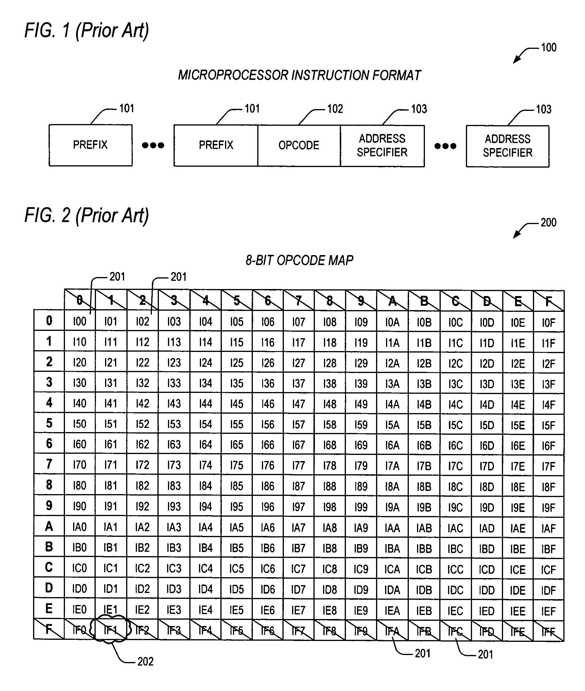
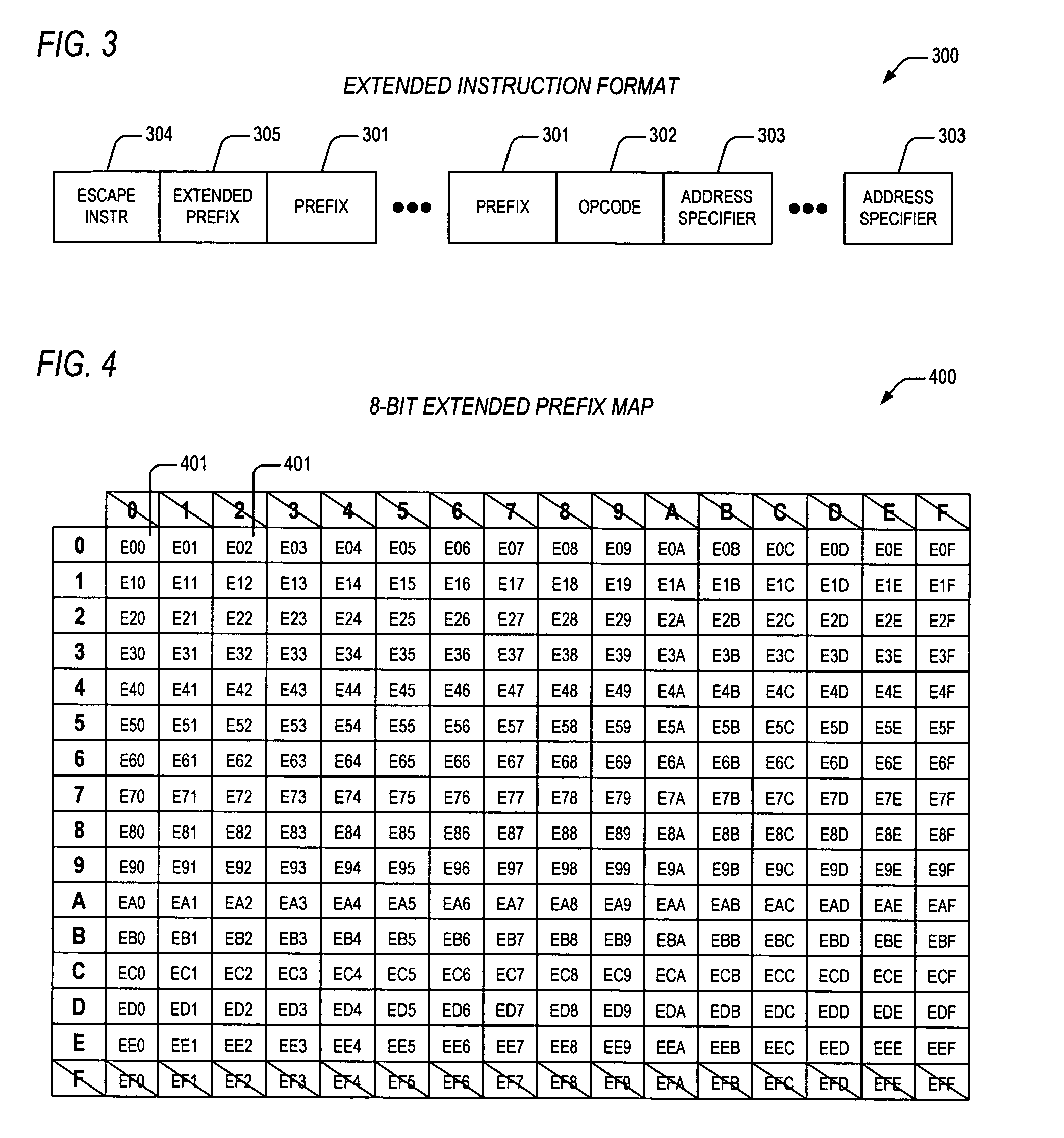
[0037]In view of the above background discussion on the techniques employed within present day microprocessors to extend the architectural features of those microprocessors beyond the capabilities of their associated instruction sets, a related art example will now be discussed with reference to FIGS. 1-2. The discussion highlights the problems that microprocessor designers r...


PUM


Abstract

Apparatus and method are provided for extending a microprocessor instruction set to allow for instruction-level specification of floating point format to be employed during execution of an associated floating point operation. The apparatus includes translation logic and extended execution logic. The translation logic translates an extended instruction into corresponding micro instructions. The extended instruction has an extended prefix and an extended prefix tag. The extended prefix specifies the floating point format. The extended prefix tag indicates the extended prefix, where the extended prefix tag is an otherwise architecturally specified opcode within an instruction set for a microprocessor. The extended execution logic is coupled to the translation logic. The extended execution logic receives the corresponding micro instructions, and executes the associated floating point operation according to the floating point format specified by the extended prefix.

Description

CROSS-REFERENCE TO RELATED APPLICATIONS[0001]This application claims the benefit of U.S. Provisional Application No. 60 / 554,299, filed on Mar. 18, 2004, which is herein incorporated by reference for all intents and purposes.[0002]This application is a continuation-in-part of co-pending U.S. patent application Ser. No. 10 / 144,595, filed on May 9, 2002, which has a common assignee and at least one common inventor, and which is herein incorporated by reference for all intents and purposes. The aforementioned co-pending U.S. patent application claims the benefit of U.S. Provisional Application Ser. No. 60 / 356,420), which was filed on Feb. 12, 2002.[0003]This application is related to the following co-pending U.S. patent applications, which are filed on the same day as this application, and which have a common assignee and common inventors.[0004]SERIALFILINGNUMBERDATETITLE11 / 001212Dec. 1, 2004APPARATUS AND METHOD FOR EXTENDING A(CNTR.2176-C1)MICROPROCESSOR INSTRUCTION SET10 / 144592May 9, ...

Claims


Application Information

Patent Timeline
Patent Type & Authority Patents(United States)
IPC IPC(8): G06F9/30G06F15/00G06F7/38G06F9/44G06F9/40G06F9/00
CPCG06F9/30025G06F9/30076G06F9/3017G06F9/30181G06F9/30185G06F9/30189G06F9/223G06F9/264G06F9/30174G06F9/30014
Inventor HENRY, G. GLENNHOOKER, RODNEY E.PARKS, TERRY
Owner VIA TECH INC
Learn More