Image forming apparatus and nozzle restoring method
a technology of forming apparatus and restoring method, which is applied in the direction of matrix printers, visual presentations, instruments, etc., can solve the problems of ink discharge failure, nozzle blockage, and increase in the viscosity of ink, so as to improve productivity, reduce wasteful consumption of liquid droplets, and perform discharge determination more efficiently
- Summary
- Abstract
- Description
- Claims
- Application Information
AI Technical Summary
Benefits of technology
Problems solved by technology
Method used
Image
Examples
first embodiment
[0113]After resetting the sub nozzles 52, the procedure returns again to the step S110 and image recording by the main nozzles 51 is continued, in addition to which discharge for discharge determination is performed at intervals of the prescribed time period t, starting from the first sub nozzle, similarly to the foregoing description. If it is judged at step S110 that there is no more image data (print data), then the procedure advances to step S170 and printing ends. The foregoing description relates to processing in a nozzle restoring method according to a According to this embodiment, it is possible to reduce unnecessary purging from the main nozzles, and hence ink can be saved and productivity can be improved.
second embodiment
[0114]Next, a nozzle restoring method relating to the second embodiment will be described.
[0115]FIG. 11 shows the discharge timing of the sub nozzles 52 in a nozzle restoring method relating to the second embodiment, and FIG. 12 is a flowchart showing a processing sequence in the nozzle restoring method of the second embodiment. In FIG. 11, t and t1 indicate the time interval at which discharge for discharge determination is performed from the sub nozzles 52, and similarly to FIG. 9, the white circles and black circles respectively indicate a discharge OK status and a discharge failure as a result of the discharge for discharge determination. Moreover, a white triangle indicates a simple discharge which is not used for discharge determination, and a cross symbol indicates that use of the sub nozzle 52 is prohibited (namely, it does not perform discharge, even if it is able to do so).
[0116]Below, the nozzle restoring method according to the present embodiment is described with refere...
third embodiment
[0143]Next, the present invention will be described.
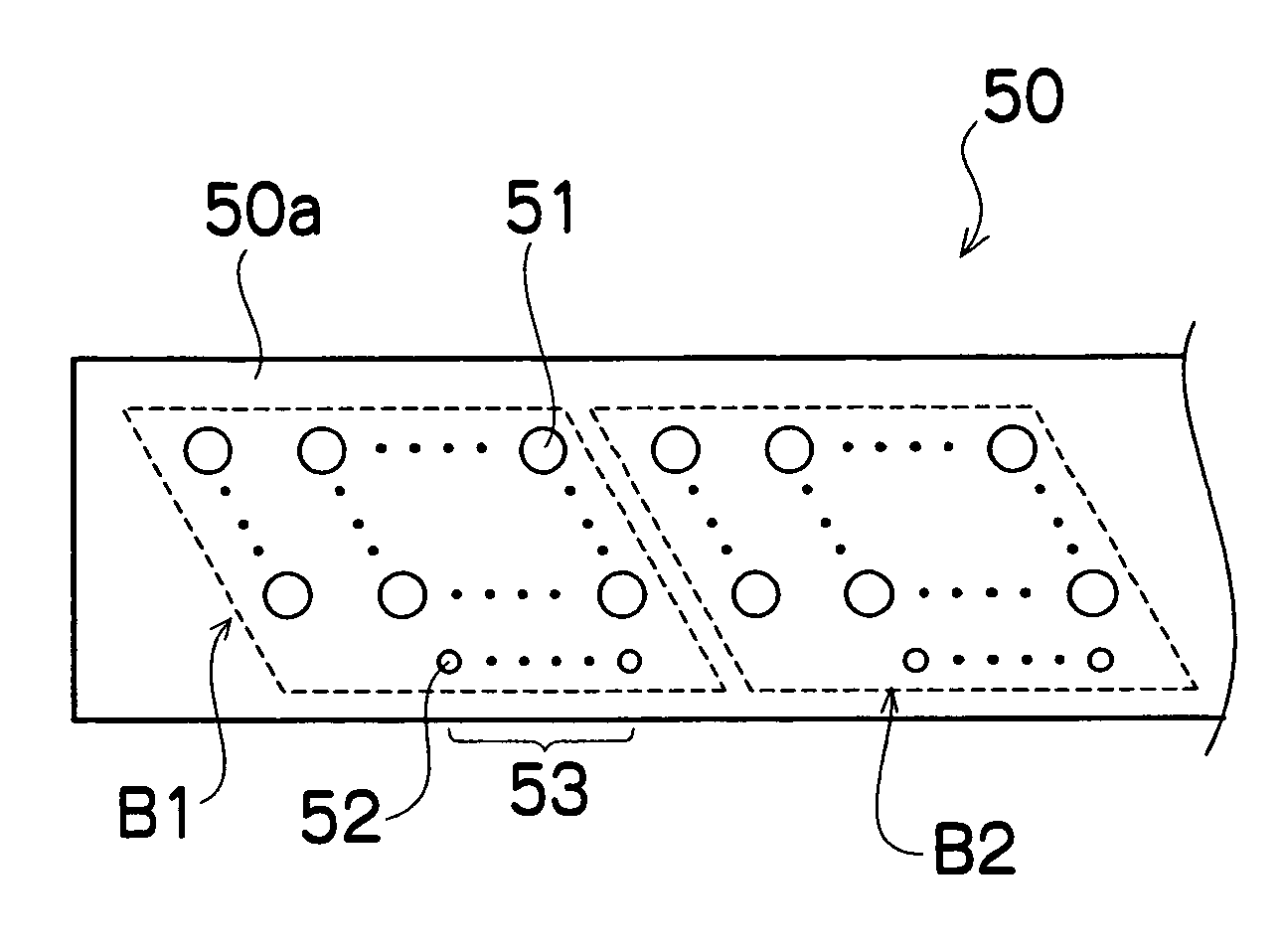
[0144]In this third embodiment, a plurality of sets of sub nozzles 52 (for instance, N sets), each set including M sub nozzles 52, are prepared for each block, and the purge timing for the main nozzles 51 is judged by using these sets of sub nozzles 52, sequentially.
[0145]Although not illustrated in the drawings, there is no particular restriction on the arrangement of the N sets of sub nozzles 52 each including M sub nozzles 52 on the nozzle surface50a (see FIG. 5). For example, the M sub nozzles 52 forming each set may be aligned in a row, in such a manner that N rows of sub nozzles 52 are formed.
[0146]FIG. 13 shows the discharge timing of the sub nozzles 52 in a nozzle restoring method relating to the third embodiment.
[0147]As shown in FIG. 13, the judgment of the initial purge timing for the main nozzles 51 is made by using the first sub nozzle set. The judgment method employed is substantially the same as that depicted in FIG....
PUM
 Abstract
Description
Claims
Application Information
 - R&D
- Intellectual Property
- Life Sciences
- Materials
- Tech Scout
- Unparalleled Data Quality
- Higher Quality Content
- 60% Fewer Hallucinations
Browse by: Latest US Patents, China's latest patents, Technical Efficacy Thesaurus, Application Domain, Technology Topic, Popular Technical Reports.
© 2025 PatSnap. All rights reserved.Legal|Privacy policy|Modern Slavery Act Transparency Statement|Sitemap|About US| Contact US: help@patsnap.com


