
Hard-disk-drive-case

a harddisk and case body technology, applied in the direction of instruments, liquid/fluent solid measurement, cabinet/cabinet/drawer, etc., can solve the problems of insufficient sealing between the case body and the hdd cover, such as insufficient waterproofness, and such weaknesses of the hdd case, so as to facilitate mounting or removal of the cover, increase the waterproofness of the case, and facilitate the cleaning of the edge pins

Inactive Publication Date: 2009-04-14
GROW UP JAPAN
View PDF5 Cites 21 Cited by
  • Summary
  • Abstract
  • Description
  • Claims
  • Application Information

AI Technical Summary

Benefits of technology

"The present invention provides a hard-disk-drive case that has a rectangular box-like metal case that houses a hard-disk drive (HDD). The case has a heat sink at the center of the inner surface of the bottom of the case body, with sound-absorbing materials on the inner surfaces of the case's walls to surround the heat sink. The case also has a cover that fits over the open top of the case body, with a heat sink at the center of the front wall of the case body. The case has a relay board on the inside of one side of the case body, with an external connector that allows for connector-to-connector or cable connection with a controller device. The case also has openings that allow for visually diagonalous connection and easy cleaning of the edge pins of the external connector. The invention aims to absorb rattling noises, prevent damage from moisture, and provide a waterproof seal for the HDD case."

Problems solved by technology

However, even in the HDD cases of Patent Documents 1 and 2, the seal between the case body and the HDD cover and the like is not sufficient, and waterproofness is not taken into consideration.
Therefore, those HDD cases have such weaknesses as the HDD being damaged by the intrusion of moisture into the case body by, for example, water sprayed in firefighting.

Method used


Image

  • Hard-disk-drive-case
  • Hard-disk-drive-case
  • Hard-disk-drive-case

Examples


embodiment 1

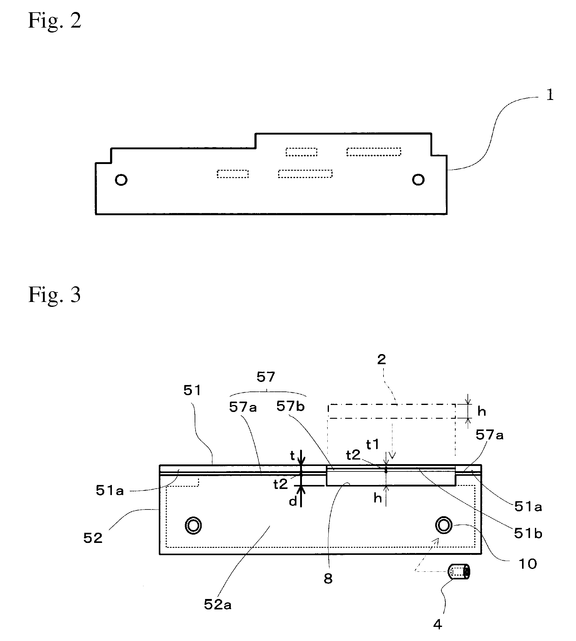
[0105]FIG. 1 is a perspective view showing the HDD case of Embodiment 1 of the present invention with the cover removed.[0106]FIG. 2 is an elevation view of the relay board of FIG. 1.[0107]FIG. 3 is an elevation view of the HDD case of Embodiment 1.[0108]FIG. 4 is a perspective view of the metal support of FIG. 1.[0109]FIG. 5 is a plan view of the seal seen from the side of the cover to which the member is applied.[0110]FIG. 6 is a perspective view of the case base seen from the bottom of the case body of Embodiment 2 of the present invention (the front and back walls are not shown).

[0111]The HDD case 100 of Embodiment 1 has a thin, rectangular box-like shape and is composed of (1) a case body 52 that has a bottom and an open top, and (2) a thin sheet-metal cover 51 that has, for example, a thickness t of approximately 2 mm, and that is made from an AI-alloy-type metal or copper-alloy-type metal, both of which are light in weight and have high thermal conductivity.

[0112]The case bod...

embodiment 2

[0171]FIG. 6 is a perspective view of the case base seen from the bottom of the case body of Embodiment 2 of the present invention (the front and back walls are not shown).[0172]For better understanding, any part of Embodiment 2 that has the same function as in Embodiment 1 is designated by the same reference number as for Embodiment 1.

[0173]Embodiment 2 includes a case base 52g on which a plural of fins 52f are formed at the bottom 52e and along the outside of the right and left walls 52c and 52c of the case body 52. The front and back walls (not shown) of the case base 52g are attached by screws to the front and back ends of the case base 52g.

[0174]The fins 52f are formed on the bottom 52e and on the outside of the right and left walls 52c and 52c, along with a plurality of parallel grooves in the lengthwise direction of the case base 52g. [0175]In this embodiment, the grooves are provided in the lengthwise direction on the bottom 52e and on the outside of the right and left wall...


PUM


Abstract

An HDD case is provided that enables direct connection of an interface connector and houses an HDD and that is superior in regard to vibration absorption, sound insulation, radiating heat, and waterproofness, and that consists of (1) a rectangular box-like case body, (2) a cover that have a heat sink, mounted via an adhesive synthetic-resin mat, and sound-absorbing materials; (3) a relay board that includes an internal connector fitted with an interface connector of the HDD, an external connector exposed to the outside so as not to protrude beyond the outside surface of the cover when the cover is closed, and wiring that connects the connectors; and (4) a waterproof seal that is applied all along the mating surface between the cover and the opening at the top of the case body and between the cover and the upper opening surface of the external connector.

Description

BACKGROUND OF THE INVENTION[0001]1. Field of the Invention[0002]The present invention relates to the structure of a hard-disk-drive (hereinafter “HDD”) case (hereinafter “HDD case”) used for storing and protecting a hard-disk drive, and more particularly relates to an HDD case that provides electricity and a direct connection for a signal connector and that is superior in regard to vibration absorption, sound insulation, heat radiation, airtightness, and waterproofing.[0003]2. Description of the Related Art[0004]An HDD is generally provided with a drive part that rotates at high speed, and therefore an HDD requires measures against the heat and vibration associated with high-speed rotation.[0005]Accordingly, it is advantageous for the HDD case to be airtight by using soundproofing materials (or sound-absorbing materials) so as to prevent the sounds caused by the rotation or vibration of the drive from escaping from the case.[0006]Also, the airtightness of an HDD case is emphasized b...

Claims


Application Information

Patent Timeline
Patent Type & Authority Patents(United States)
IPC IPC(8): H05K5/00G06F1/16H05K7/20G06F1/20H05K5/06H05K7/00H01G9/10
CPCG11B33/08G11B33/124G11B33/1426G11B33/1446
Inventor KOBAYASHI, TOSHIHIRO
Owner GROW UP JAPAN
Learn More