
Bulk stamped amorphous metal magnetic component

a magnetic component and amorphous metal technology, applied in the field of amorphous metal magnetic components, can solve the problems of long-standing consideration of unsuitability for bulk magnetic components, tooling and manufacturing costs, and the tendency of fabrication tools and dies to wear more rapidly, so as to reduce stress, reduce manufacturing time, and simplify manufacturing

Inactive Publication Date: 2009-03-24
METGLAS INC
View PDF25 Cites 29 Cited by
  • Summary
  • Abstract
  • Description
  • Claims
  • Application Information

AI Technical Summary

Benefits of technology

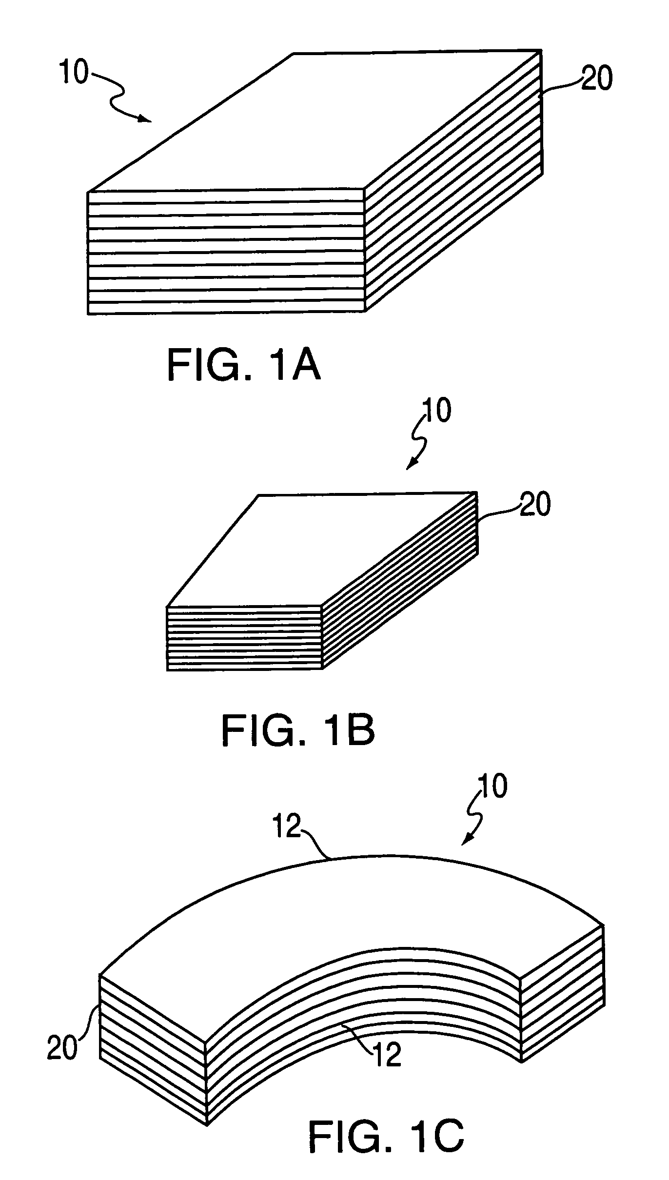
[0012]The present invention provides a low-loss, bulk amorphous metal magnetic component having the shape of a polyhedron or other three-dimensional (3-D) shape and being comprised of a plurality of layers of ferromagnetic, amorphous metal strips. Also provided by the present invention is a method for making a bulk amorphous metal magnetic component. The magnetic component is operable at frequencies ranging from about 50 Hz to 20,000 Hz and exhibits improved performance characteristics when compared to silicon-steel magnetic components operated over the same frequency range. A magnetic component constructed in accordance with the present invention and excited at an excitation frequency “f” to a peak induction level “Bmax” will have a core loss at room temperature less than “L” wherein L is given by the formula L=0.0074 f (Bmax)1.3+0.000282 f1.5 (Bmax)2.4, the core loss, the excitation frequency and the peak induction level being measured in watts per kilogram, hertz, and teslas, respectively. The magnetic component will have (i) a core-loss of less than or approximately equal to 1 watt-per-kilogram of amorphous metal material when operated at a frequency of approximately 60 Hz and at a flux density of approximately 1.4 Tesla (T); (ii) a core-loss of less than or approximately equal to 12 watts-per-kilogram of amorphous metal material when operated at a frequency of approximately 1000 Hz and at a flux density of approximately 1.0 T, or (iii) a core-loss of less than or approximately equal to 70 watt-per-kilogram of amorphous metal material when operated at a frequency of approximately 20,000 Hz and at a flux density of approximately 0.30 T.
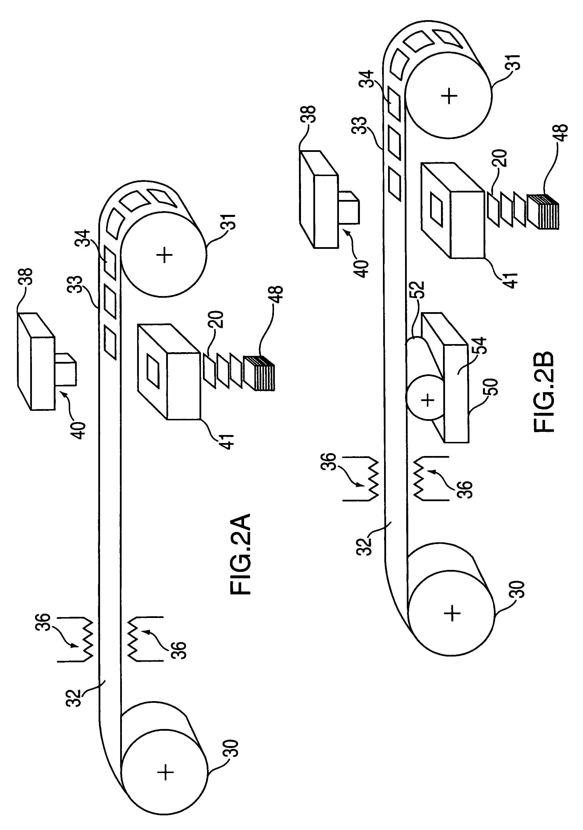
[0015]The present invention is also directed to a bulk amorphous metal component constructed in accordance with the above-described methods. In particular, bulk amorphous metal magnetic components constructed in accordance with the present invention are especially suited for amorphous metal components such as tiles for poleface magnets in high performance MRI systems, television and video systems, and electron and ion beam systems. Bulk amorphous magnetic components constructed in accordance with the present invention are also useful for non-toroidal shaped inductors such as C-cores, E-cores and E / I-cores, wherein the terminology C, E and E / I is descriptive of the cross-sectional shape of the components. The advantages afforded by the present invention include simplified manufacturing, reduced manufacturing time, reduced stresses (e.g., magnetostrictive) encountered during construction of bulk amorphous metal components, and optimized performance of the finished amorphous metal magnetic component.

Problems solved by technology

Although amorphous metals offer superior magnetic performance when compared to non-oriented electrical steels, they have long been considered unsuitable for use in bulk magnetic components such as the tiles of poleface magnets for MRI systems due to certain physical properties of amorphous metal and the corresponding fabricating limitations.
Consequently, conventional cutting and stamping processes cause fabrication tools and dies to wear more rapidly.
The resulting increase in the tooling and manufacturing costs makes fabricating bulk amorphous metal magnetic components using such techniques as conventionally practiced commercially impractical.
The thinness of amorphous metals also translates into an increased number of laminations in the assembled components, further increasing the total cost of the amorphous metal magnetic component.
However, amorphous metal is a very hard material making it very difficult to cut or form easily, and once annealed to achieve peak magnetic properties, it becomes very brittle.
This makes it difficult and expensive to use conventional approaches to construct a bulk amorphous metal magnetic component.
The brittleness of amorphous metal may also cause concern for the durability of the bulk magnetic component in an application such as an MRI system.
Another problem with bulk amorphous metal magnetic components is that the magnetic permeability of amorphous metal material is reduced when it is subjected to physical stresses.
This results in higher magnetic losses, increased heat production, and reduced power.

Method used


Image

  • Bulk stamped amorphous metal magnetic component
  • Bulk stamped amorphous metal magnetic component
  • Bulk stamped amorphous metal magnetic component

Examples


example 1

Preparation and Electro-Magnetic Testing of a Stamped Amorphous Metal Arcuate Component

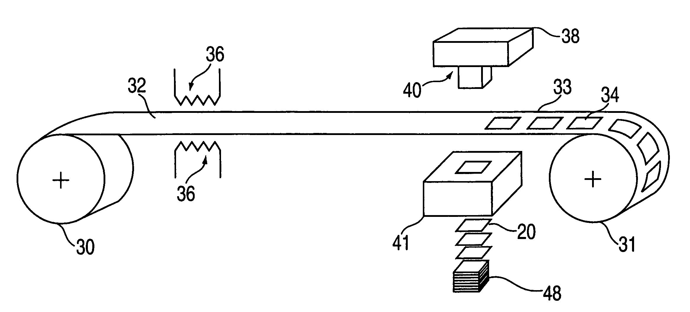
[0066]Fe80B11Si9 ferromagnetic amorphous metal ribbon, approximately 60 mm wide and 0.022 mm thick, is stamped to form individual laminations, each having the shape of a 90° segment of an annulus 100 mm in outside diameter and 75 mm in inside diameter. Approximately 500 individual laminations are stacked and registered to form a 90° arcuate segment of a right circular cylinder having a 12.5 mm height, a 100 mm outside diameter, and a 75 mm inside diameter, as illustrated in FIG. 1c. The cylindrical segment assembly is placed in a fixture and annealed in a nitrogen atmosphere. The anneal consists of: 1) heating the assembly up to 365° C.; 2) holding the temperature at approximately 365° C. for approximately 2 hours; and, 3) cooling the assembly to ambient temperature. The cylindrical segment assembly is removed from the fixture. The cylindrical segment assembly is placed in a second fixture, vacuum...

example 2

High Frequency Electro-Magnetic Testing of a Stamped Amorphous Metal Arcuate Component

[0068]A cylindrical test assembly comprising four stamped amorphous metal arcuate components is prepared as in Example 1. Primary and secondary electrical windings are fixed to the test assembly. Electrical testing is carried out at 60, 1000, 5000, and 20,000 Hz and at various flux densities. Core loss values are compiled in Tables 1, 2, 3, and 4 below. As shown in Tables 3 and 4, the core loss is particularly low at excitation frequencies of 5000 Hz or higher. Thus, the magnetic component of the invention is especially suited for use in poleface magnets for MRI systems.

[0069]

TABLE 1Core Loss @ 60 Hz (W / kg)MaterialCrystallineCrystallineCrystallineCrystallineFe-3% SiFe-3% SiFe-3% SiFe-3% Si(25 μm)(50 μm)(175 μm)(275 μm)National-National-National-National-AmorphousArnoldArnoldArnoldArnoldFluxFe80B11Si9 MagneticsMagneticsMagneticsMagneticsDensity(22 μm)SilectronSilectronSilectronSilectron0.3 T0.100.20...

example 3

High Frequency Behavior of Low-Loss Bulk Amorphous Metal Components

[0073]The core loss data of Example 2 above are analyzed using conventional non-linear regression methods. It is determined that the core loss of a low-loss bulk amorphous metal component comprised of Fe80B11Si9 amorphous metal ribbon can be essentially defined by a function having the form

L(Bmax, f)=c1f(Bmax)n+c2fq(Bmax)m.

Suitable values of the coefficients c1 and c2 and the exponents n, m, and q are selected to define an upper bound to the magnetic losses of the bulk amorphous metal component. Table 5 recites the losses of the component in Example 2 and the losses predicted by the above formula, each measured in watts per kilogram. The predicted losses as a function of f (Hz) and Bmax (Tesla) are calculated using the coefficients c1=0.0074 and c2=0.000282 and the exponents n=1.3, m=2.4, and q=1.5. The loss of the bulk amorphous metal component of Example 2 is less than the corresponding loss predicted by the formul...


PUM


Abstract

A bulk amorphous metal magnetic component has a plurality of laminations of ferromagnetic amorphous metal strips adhered together to form a generally three-dimensional part having the shape of a polyhedron. The component is formed by stamping, stacking and bonding. The bulk amorphous metal magnetic component may include an arcuate surface, and an implementation may include two arcuate surfaces that are disposed opposite each other. The magnetic component may be operable at frequencies ranging from between approximately 50 Hz and 20,000 Hz. When the component is excited at an excitation frequency “f” to a peak induction level Bmax, it may exhibit a core-loss less than “L” wherein L is given by the formula L=0.0074 f (Bmax)1.3+0.000282 f1.5 (Bmax)2.4, said core loss, said excitation frequency and said peak induction level being measured in watts per kilogram, hertz, and teslas, respectively.

Description

[0001]This application is a Divisional Application of Ser. No. 10 / 279,250, now U.S. Pat. No. 7,011,718, filed Oct. 24, 2002. This application claims priority benefit under 35 USC § 120 of provisional U.S. Application No. 60 / 200,563 filed Apr. 28, 2000, U.S. Pat. No. 6,552,639, filed Apr. 25, 2001 and U.S. Pat. No. 7,011,718, filed Oct. 24, 2002, the disclosures of which are incorporated herein by reference.BACKGROUND OF THE INVENTION[0002]1. Field of the Invention[0003]This invention relates to amorphous metal magnetic components; and more particularly, to a generally three-dimensional bulk stamped amorphous metal magnetic component for large electronic devices such as magnetic resonance imaging systems, television and video systems, and electron and ion beam systems.[0004]2. Description of the Prior Art[0005]Magnetic resonance imaging (MRI) has become an important, non-invasive diagnostic tool in modern medicine. An MRI system typically comprises a magnetic field generating device....

Claims


Application Information

Patent Timeline
Patent Type & Authority Patents(United States)
IPC IPC(8): B26D1/00H01F1/153H01F41/02
CPCH01F1/15308H01F1/15358H01F41/0226Y10T29/49078Y10T29/49073Y10T29/4902Y10T83/04Y10T83/9418Y10T83/9423Y10T83/9454
Inventor DECRISTOFARO, NICHOLAS J.FISH, GORDON E.LINDQUIST, SCOTT M.STAMATIS, PETER J.
Owner METGLAS INC
Learn More