
Three-dimensional node structure

Inactive Publication Date: 2009-03-10
THYSSENKRUPP STEEL EURO AG
View PDF26 Cites 16 Cited by
  • Summary
  • Abstract
  • Description
  • Claims
  • Application Information

AI Technical Summary

Benefits of technology

[0011]A special advantage of the present invention is that by cutting through the first hollow profile with a subsequent bending operation, an extremely small bending radius may be achieved in comparison to conventional joint structures manufactured using hydroforming, which allows a very compact and thus weight-optimized construction of the joint structure. Simultaneously, very high rigidity is achieved, since the lateral walls of the second hollow profile pressing against the ends of the first hollow profile reinforce the joint structure as bulkhead plates of the first hollow profile. The use of additional reinforcing components in the form of support plates or other things is therefore no longer necessary, which leads to a weight-favorable construction.
[0012]In one embodiment of the present invention, the contours of the two hollow profiles press against one another without gaps. Improved distribution of the forces acting on the entire support frame in case of a crash thus results, through which the danger of individual elements of the support frame collapsing is reduced. In particular, the occurrence of punctual load peaks is avoided, since the hollow profiles press against one another in a form-fitting way. Since such three-dimensional joint structures are used especially in the region of the passenger cell, increased protection for the vehicle occupants thus results in case of a crash.
[0013]According to a further embodiment of the present invention, the ends of the first hollow profile facing toward one another have projecting edge regions which press against the second hollow profile. These form easily usable attachment zones for joining the two hollow profiles through welding, soldering, or another joining method.
[0014]If the joint structure is used in heavily loaded regions of the vehicle support frame, it is expedient for quadrilateral cutouts curved corresponding to the edge radius, which extend over the entire edge radius, to be cut out symmetrically to the separating cut along the separating cut in the region of the edges of the first hollow profile. A notching effect in the corners of the ends of the first hollow profile facing toward one another caused by a load is thus largely avoided. In this context, it has been shown to be especially advantageous if the cut-out cutouts have rounded corners. If the joint structure is used in less loaded regions of the vehicle support frame, this embodiment may be dispensed with for more cost-effective manufacture.
[0015]Furthermore, the object specified above is achieved by a method for manufacturing the joint structure according to the present invention having the following steps:
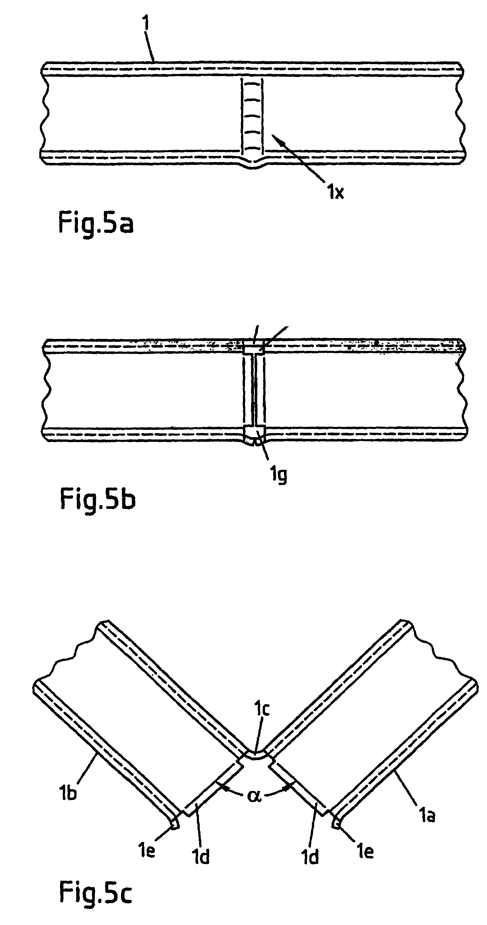
[0016]a) cutting through a first hollow profile, having at least one planar side, around its circumference in one single plane except for a web lying in the planar side,

Problems solved by technology

Since such three-dimensional joint structures are used especially in the region of the passenger cell, increased protection for the vehicle occupants thus results in case of a crash.

Method used


Image

  • Three-dimensional node structure
  • Three-dimensional node structure
  • Three-dimensional node structure

Examples


Embodiment Construction

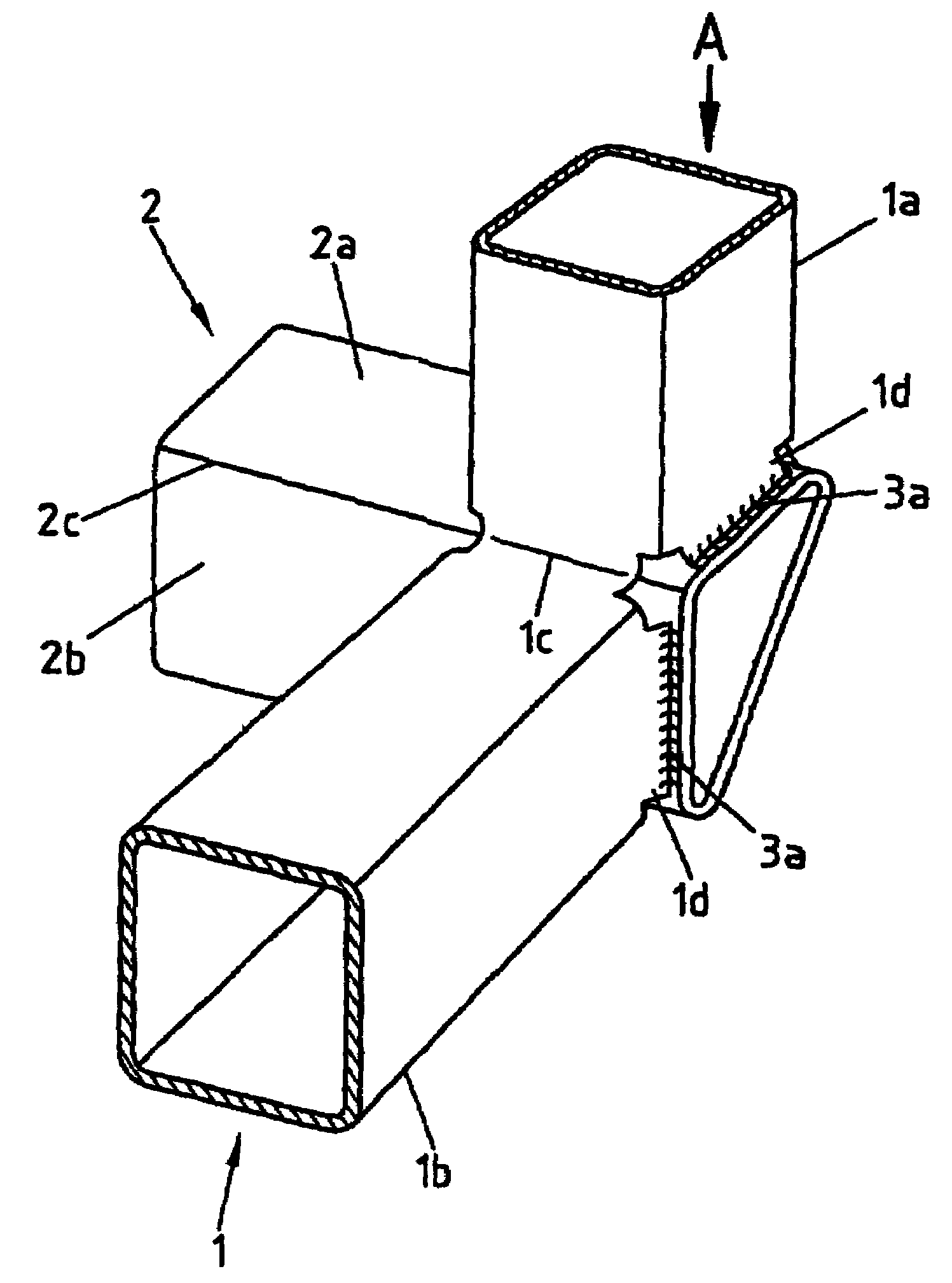
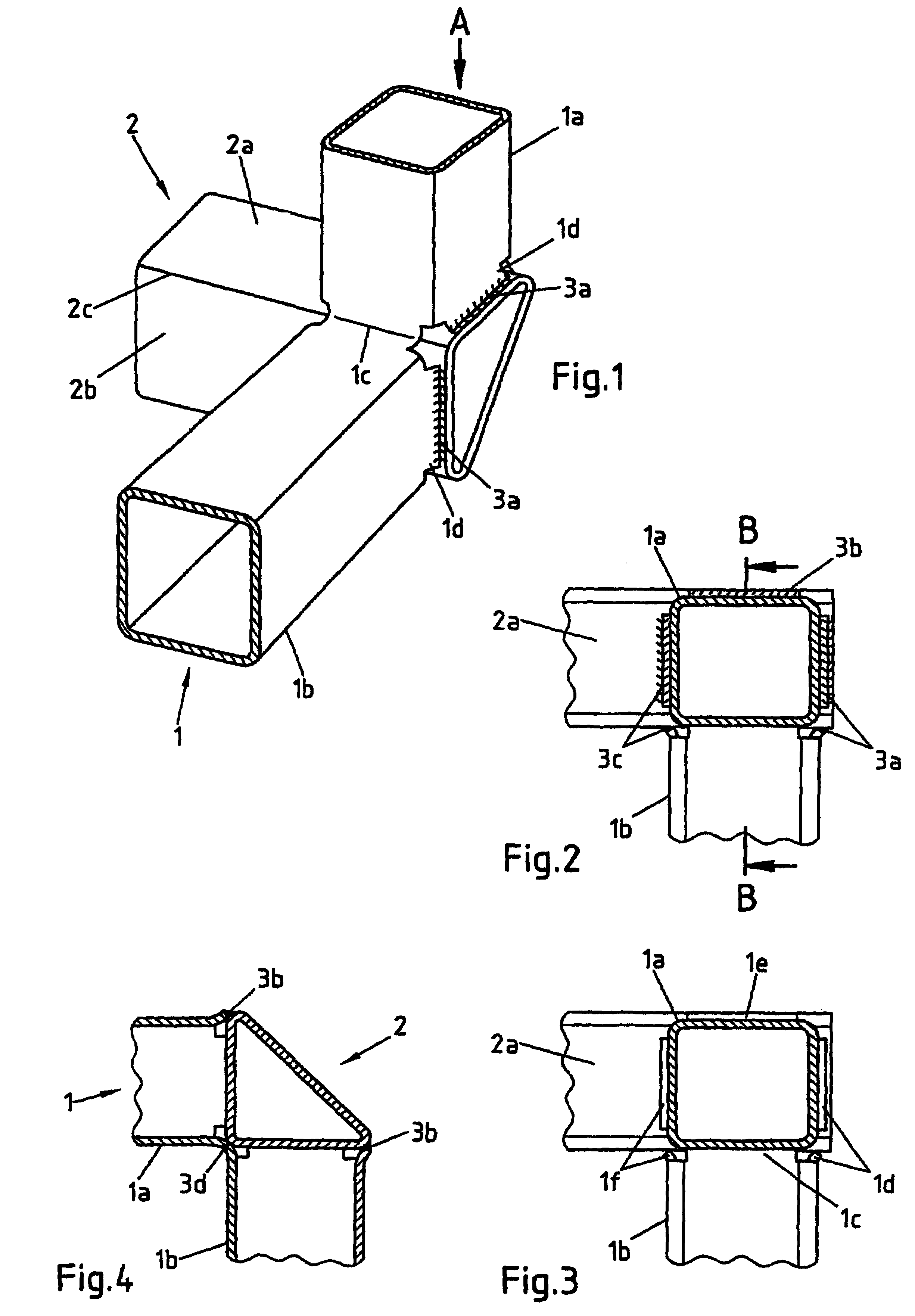
[0030]The three-dimensional joint structure illustrated in FIG. 1 comprises two hollow profiles 1, 2, which together form the shape of a tripod and are integrally joined to one another. The first hollow profile 1, which has an essentially square cross-section, is cut through around its circumference except for a web 1c and bent around the web 1c, so that two ends 1a, 1b of the hollow profile 1 facing toward one another result. The second hollow profile 2 has a cross-section in the form of an equilateral triangle and its leg sides 2a, 2b press against the ends 1a, 1b of the first hollow profile 1. In this case, the angle between the leg sides 2a, 2b corresponds to the bending angle, so that the leg sides 2a, 2b press against the faces of the ends 1a, 1b of the hollow profile 1 without a gap as much as possible.

[0031]The two ends 1a, 1b of the hollow profile 1 have bent-over edge regions 1d, 1e, 1f along their separating cut, which press against the leg sides 2a, 2b of the hollow prof...


PUM


Abstract

A three-dimensional joint structure of a support frame for vehicles can include two hollow profiles, of which the first hollow profile has at least one planar side and is cut through around its circumference except for a web lying in this planar side and is bent around this web. The second hollow profile has at least two planar sides that press against the ends of the first hollow profile resulting from the cutting and bending. The two hollow profiles are integrally joined to one another at the edge region of the ends.

Description

BACKGROUND OF THE INVENTION[0001]The present invention relates to a three-dimensional joint structure, formed by two hollow profiles, of a support frame for vehicles, and a method for its manufacture.[0002]Joint structures for vehicle support frames are known in different embodiments. A three-dimensional joint, structure having a connecting part for connecting elements of a vehicle support frame is described in EP 0568 213 B1. The connecting part comprises a preferably extruded U-profile having two side plates and a web plate which connects the side plates, in which a support element is laid and bonded thereto through gluing. Essentially cuboid attachment parts are attached to the outsides of one side plate and the web plate, on whose faces further support elements may be placed and glued to the connecting part, so that as a result the support elements may be joined into a stable joint structure having a compact construction. However, this construction has the disadvantage that it r...

Claims


Application Information

Patent Timeline
IPC IPC(8): B62D21/00B62D21/02B62D23/00B62D25/00B62D27/02
CPCB62D23/005B62D25/00B62D27/023Y10T403/73Y10T403/342Y10T403/347Y10T403/42Y10T403/4309Y10T403/7096Y10T403/479F16B2200/67
Inventor PATBERG, LOTHAR
Owner THYSSENKRUPP STEEL EURO AG
Learn More