
Cable or the like protecting and guiding device

A pipeline protection and guiding device technology, applied in the installation of cables, cable arrangement between relatively moving parts, drag chains, etc., can solve the problems of hindering sliding contact action, increasing the bending radius, and unable to eliminate the enlargement of the device, etc. Achieve the effect of miniaturization and reduction of bending radius

Inactive Publication Date: 2011-08-03
TSUBAKIMOTO CHAIN CO
View PDF5 Cites 12 Cited by
  • Summary
  • Abstract
  • Description
  • Claims
  • Application Information

AI Technical Summary

Problems solved by technology

[0005] However, the conventional cable protection guide device 500 exemplified in Patent Document 1, such as Figure 12 to Figure 15 As shown, since the sliding contact bottom 541 of the shoe 540 has a rectangular sliding contact bottom surface 541a that is in sliding contact with each other up and down on the inner peripheral side of the cable bend, when the cable is fixed between the fixed end and the cable moving end When the cable length direction is turned back and moved, the sliding contact bottoms 541, 541 of the adjacent shoes 540, 540 in the cable length direction contact and interfere with each other, and the bending radius is increased. The problem of increasing the size of the device due to the increase of the bending radius
[0006] Furthermore, if the size of the rectangular sliding contact bottom surface 541a is reduced along the length direction of the cable to achieve miniaturization, the bending radius at the time of turning back can be reduced and the shape can be compacted, but it is easy to cause the upper and lower sides of the inner peripheral side of the bending of the cable. The sliding contact bottoms 541, 541 of the opposing shoes 540, 540 engage with each other concave and convex, which hinders the continuous sliding contact action, so there is no connection between the fixed end of the cable and the moving end of the cable in the length direction of the cable. The problem of smooth relative movement of reentry

Method used


Image

  • Cable or the like protecting and guiding device
  • Cable or the like protecting and guiding device
  • Cable or the like protecting and guiding device

Examples


Embodiment Construction

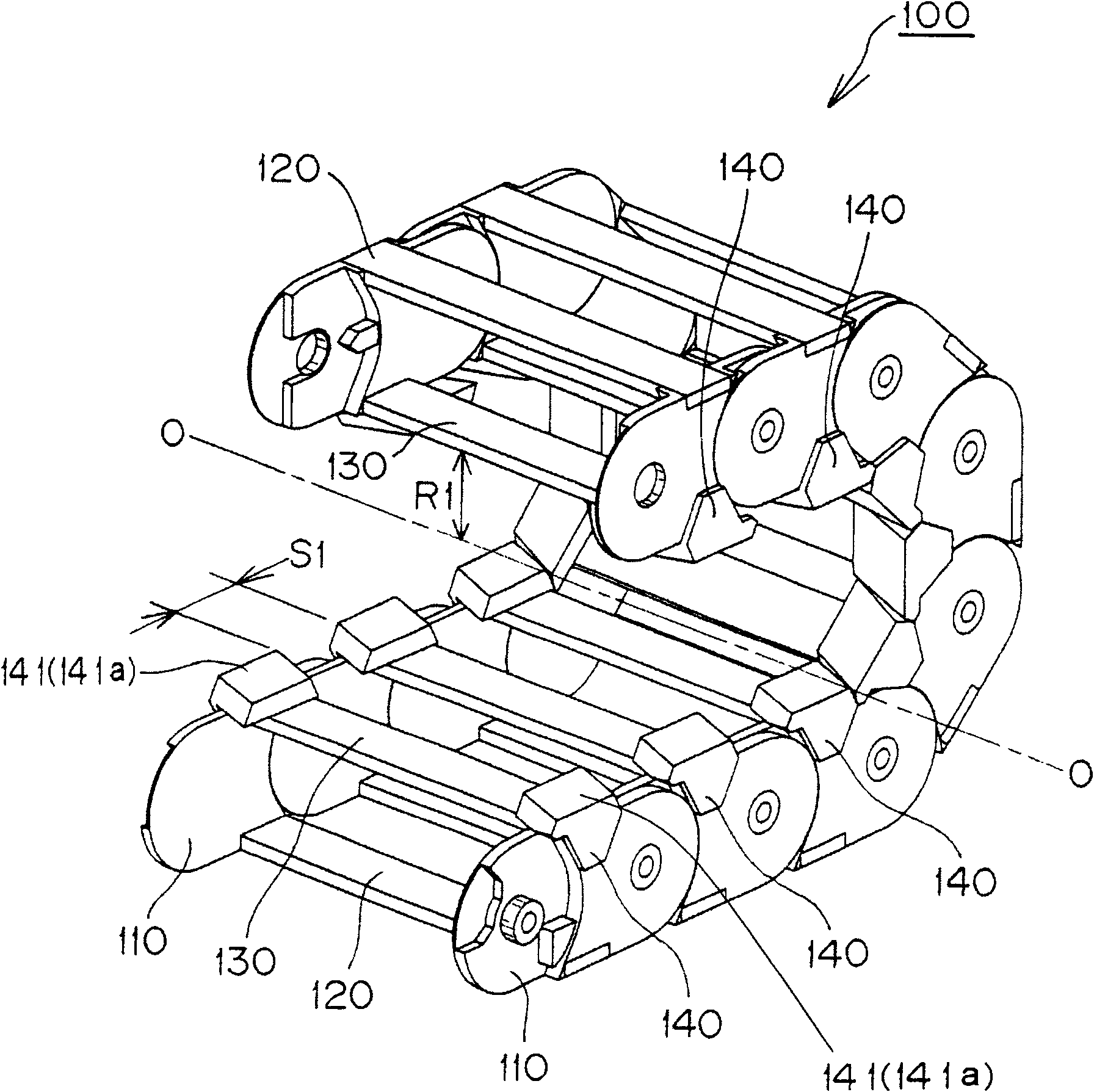
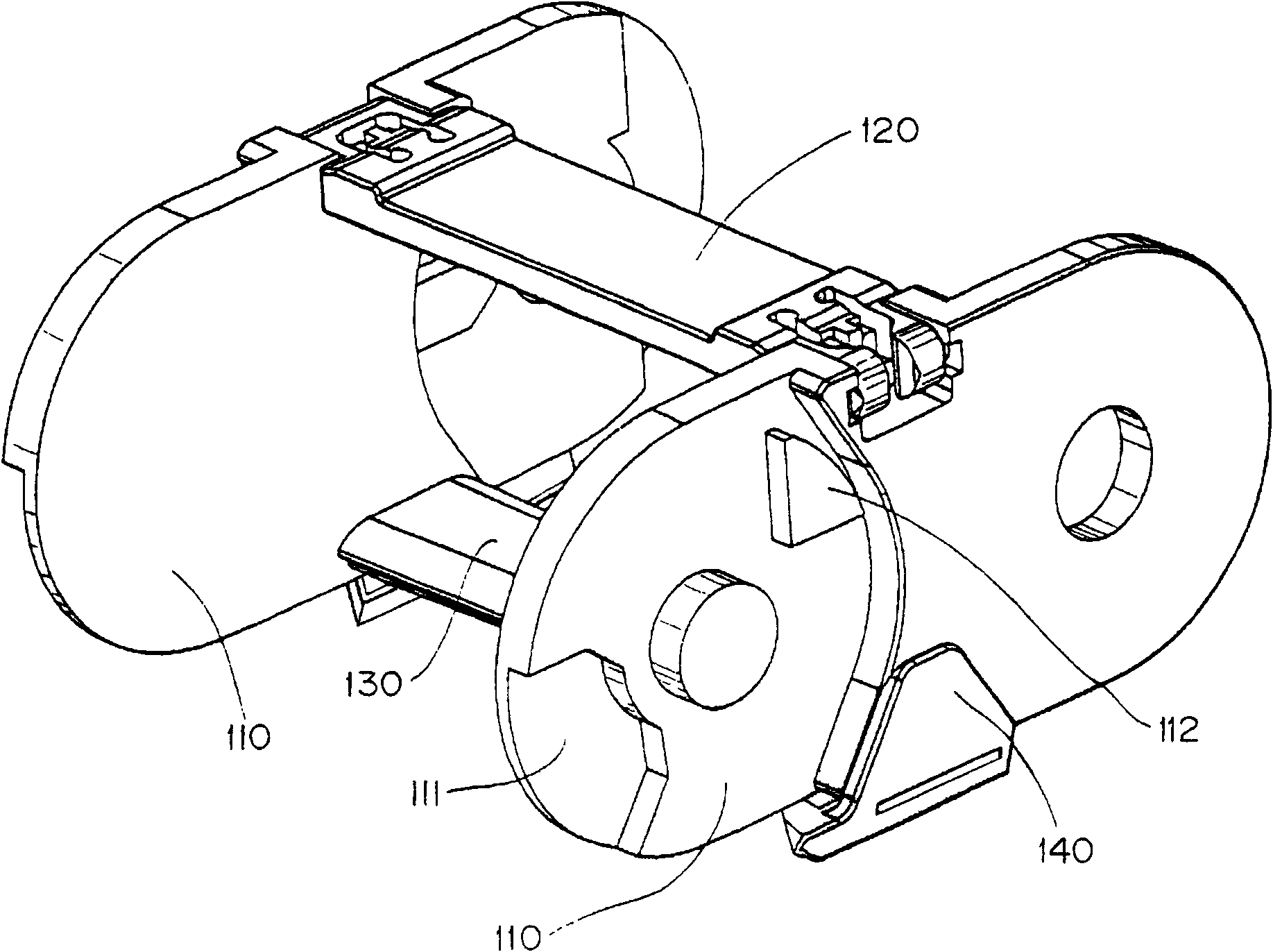
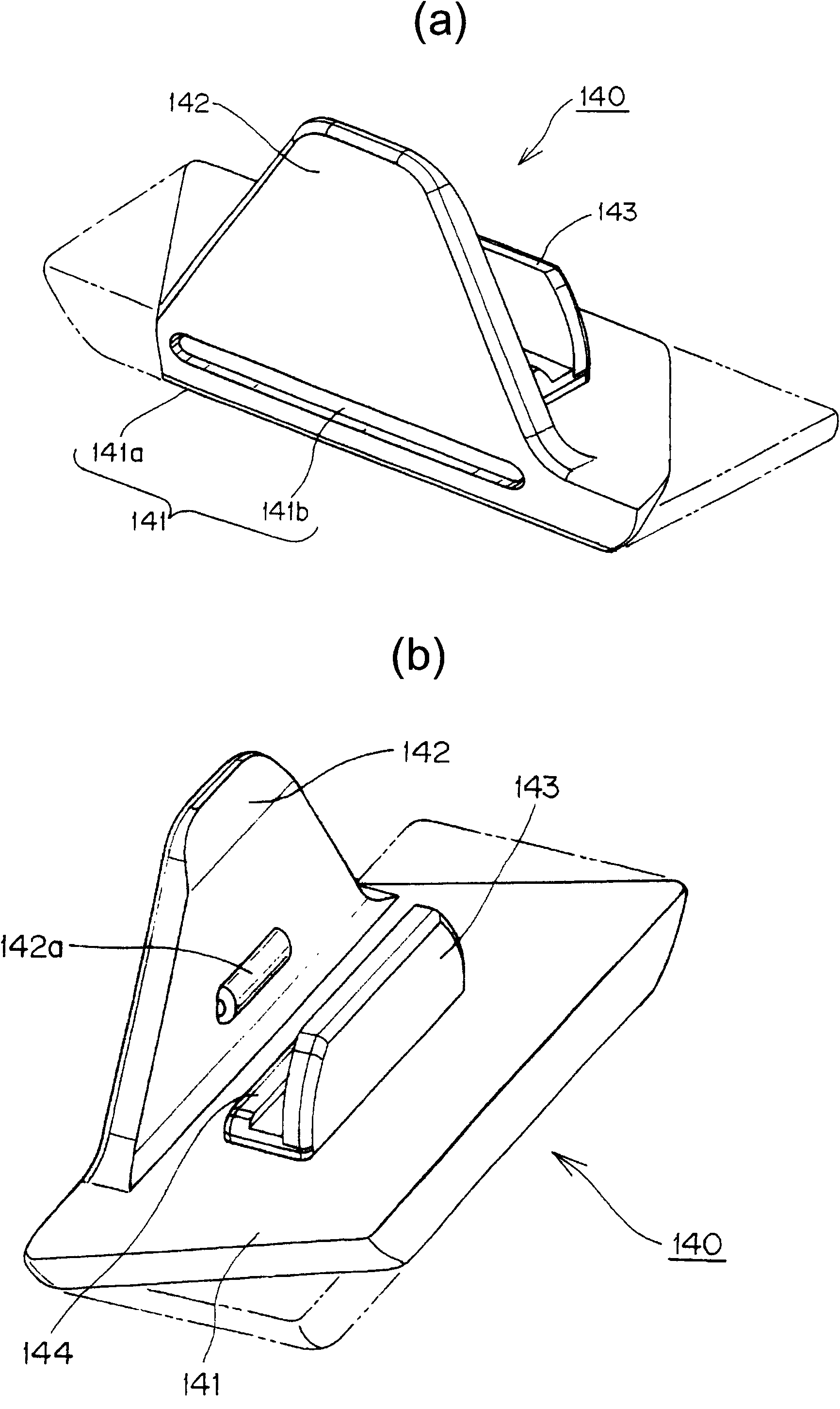
[0032] The invention relates to a cable and / or pipeline protection and guiding device, which connects a plurality of chain link frames along the length direction of the cables, and makes the cables and / or pipelines inserted through the chain link frames A cable and / or pipeline protection and guiding device that moves between the fixed end and the moving end of the cable and moves back and forth in the length direction of the cable. The cable bending outer peripheral side of the joint plate and the connecting plate on the cable bending inner peripheral side are composed of a joint plate, and it is characterized in that the sliding contact bottom of the shoe provided on the cable bending inner peripheral side of the link plate has a parallelogram sliding contact bottom surface , and the bottom surface of the sliding contact is in sliding contact with each other on the inner peripheral side of the cable bending, as long as the bending radius between the fixed end of the cable and ...


PUM


Abstract

The present invention provides a cable protecting and guiding device with a reduced radius of flexion formed when the device is bent back in a cable longitudinal direction between cable fixing and moving ends and which attains a smooth movement by continuously sliding along slidable-contact bottom portions of shoes disposed on upper and lower parts of the flexed cable inner peripheral side. In the cable protecting and guiding device (100), a slidable-contact bottom portion (141) of a shoe (140) provided on the flexed cable inner peripheral side of a pair of link plates (110, 110) disposed apart in the lateral direction has a parallelogram slidable-contact bottom surface (141a) that slidably contacts between upper and lower shoes on the flexed cable inner peripheral side.

Description

technical field [0001] The present invention relates to, for example, flexible cables and / or pipelines such as cables for connecting moving parts such as industrial machines and vehicles and stationary parts for transmission of electric signals and power supply, hoses for supplying oil pressure and air pressure, etc. Cable and / or pipeline protection guides for safe and reliable protection guides. Background technique [0002] In the conventional cable and / or pipeline protection and guiding device, a pair of link plates arranged separately on the left and right and connecting plates respectively mounted on the outer peripheral side of the cable bending and the inner peripheral side of the cable bending of the link plates constitute the link. The frame body is connected with a plurality of the chain link frame bodies along the length direction of the cable in such a way that the bending radius is limited to a certain value or more. [0003] In addition, the cable and / or pipel...

Claims


Application Information

Patent Timeline
Patent Type & Authority Applications(China)
IPC IPC(8): F16G13/16
CPCF16G13/16H02G3/0475H02G11/00
Inventor 山下胜英
Owner TSUBAKIMOTO CHAIN CO
Learn More