Auxiliary control apparatus for micro-manipulators used in ultrasonic bonding machines

Active Publication Date: 2009-02-17
MILLER CHARLES F
View PDF12 Cites 5 Cited by
  • Summary
  • Abstract
  • Description
  • Claims
  • Application Information

AI Technical Summary

Benefits of technology

[0011]An object of the present invention is to provide an auxiliary control apparatus for a micro-manipulator used to position a bonding tool of an ultrasonic bonding machine, the apparatus having a motion control mechanism which is mechanically coupleable to an input control member of a manipulator input mechanism of the micro-manipulator to thereby effect motions of the micro-manipulator and bonding tool to motions of a hand control knob and arm of the apparatus.
[0017]Briefly stated, the present invention comprehends an apparatus for improving performance capabilities of micro-manipulators of a type which are used to position the tip of an ultrasonic tool tip relative to bonding sites on a workpiece. Specifically, the invention comprehends an auxiliary control apparatus for micro-manipulators which includes a manually operable motion control mechanism that is mechanically coupleable to the input control member of a micro-manipulator of an ultrasonic bonding machine, and mountable to the machine at a location more remote from a bonding tool positionable by the machine than the input control member. In a preferred embodiment of the invention, the auxiliary control mechanism is mounted to the machine at a location laterally offset further from the bonding tool than the micro-manipulator control arm, thus expanding the lateral extent of useable working space below the bonding tool and in front of the machine, and thereby enabling the machine to be conveniently used to make bonds on larger workpieces. The apparatus according to the present invention is intended primarily for use with micro-manipulators which utilize a 4-bar parallelogram linkage that has an output coupling arm coupled to a tool support plate movably mounted to a machine support structure and so constructed as to effect motions of the tip of an ultrasonic bonding tool mounted to the tool support plate in three orthogonal directions which are parallel to those of a micro-manipulator control knob attached to an input member of a micro-manipulator input mechanism. Such micro-manipulators are usually constructed so that magnitudes of tool tip motions in each of the coordinate directions are predetermined ratios of input control knob motions, e.g., ⅛th, thus enabling the tool tip to be precisely positioned relative to workpiece bonding sites in spite of small tremors in the hand of the operator who is manipulating the control knob.
[0026]The adapter coupling joint has a pivot pin which is disposed perpendicularly to a flat upper surface of the longitudinally disposed input member of the micro-manipulator. Thus, the adapter coupling joint enables the micro-manipulator input arm to be translated longitudinally in fore-and-aft, plus / minus Y directions in unison with the auxiliary control knob of the auxiliary control apparatus, when the trolley block of the 4-bar linkage assembly of the auxiliary control mechanism is translated fore-and-aft in response to fore-and-aft manipulations of the auxiliary hand control knob by an operator. Also, the forward end of the micro-manipulator input member attached to the adapter coupler is translated laterally left and right, a minus and plus X, directions, in response to left and right motions of the auxiliary hand control knob of the auxiliary control apparatus. In addition, pivotal motion of the rear lateral linkage bar about the laterally disposed, mechanism support pivot axle in response to up / down, plus / minus Z direction translations of the auxiliary hand control knob tilts the plane of the linkage assembly up or down from a generally horizontal quiescent orientation, thereby causing the micro-manipulator input arm and coupler to be translated up and down in unison with the auxiliary hand control knob.

Problems solved by technology

However, increasing the length of the control arm would undesirably alter the kinematic scaling ratios of tool tip motions to input control knob motions.

Method used


Image

  • Auxiliary control apparatus for micro-manipulators used in ultrasonic bonding machines
  • Auxiliary control apparatus for micro-manipulators used in ultrasonic bonding machines
  • Auxiliary control apparatus for micro-manipulators used in ultrasonic bonding machines

Examples


Embodiment Construction

[0040]An understanding of the structure and function of the present invention, and of the most novel and advantageous features thereof, may be facilitated by a review of prior art micro-manipulator mechanisms for ultrasonic bonding machines, of the type the present invention is intended to be connected. Details of the structure and function in addition to those disclosed below may be found in the present inventors' patents listed below, and the entire specifications of those patents are hereby incorporated by reference into the present application: U.S. Pat. No. 5,871,136, Micro-positioner For Ultrasonic Bonding; U.S. Pat. No. 6,164,514, Micro-manipulator For Ultrasonic Bonding With Orthogonal Tool Support Slides.

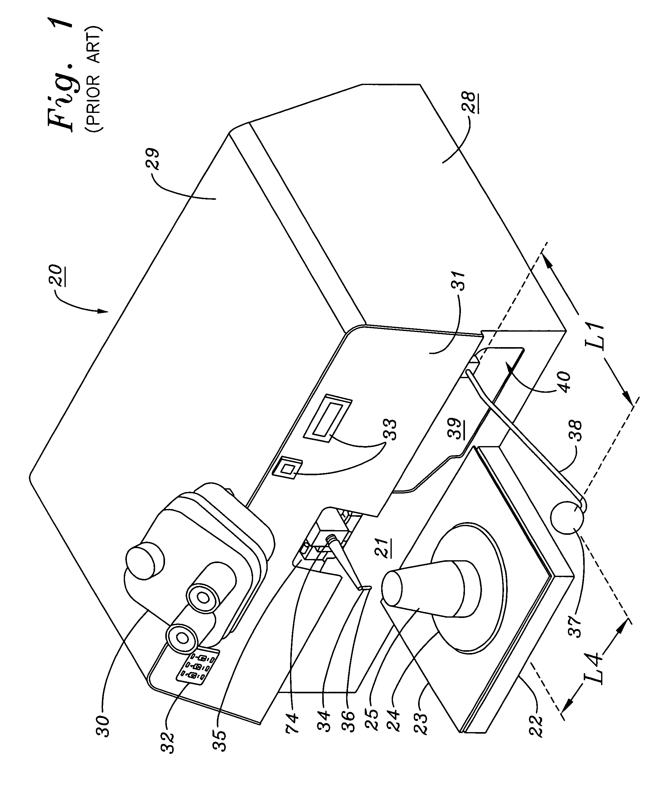
[0041]FIG. 1 shows a prior art micro-manipulator apparatus 40 according to the present invention, operably interconnected with other elements to comprise a manually operable ultrasonic bonding machine 20. Bonding machine 20 is used typically to make ultrasonic wire bonds on...


PUM

PropertyMeasurementUnit
Forceaaaaaaaaaa
Ratioaaaaaaaaaa

Abstract

An auxiliary control apparatus mechanically couples forces exerted on a manually operable auxiliary hand control knob to an input member of a micro-manipulator of the type used to move a point of an object such as an ultrasonic bonding tool tip relative to a workpiece in scaled ratios of motions at an end of the micro-manipulator input member. The apparatus includes a 4-bar parallelogram linkage which is mounted to a structural support member of a micro-manipulator, and which includes a rear laterally disposed lateral linkage bar pivotably connected to inner and outer parallel longitudinally disposed linkage bars which are pivotably coupled at front ends thereof to a front laterally disposed linkage bar. An input control arm protrudes downwardly from and forward of the outer longitudinal linkage bar, and a connector arm protrudes laterally inwardly from an inner end of the front lateral linkage bar, inwardly of the inner longitudinal linkage bar; the inner lateral end of the connector arm is pivotably connected to a forward end of the micro-manipulator input member. The rear lateral linkage bar is pivotably mounted onto a pivot axle which protrudes laterally outwards from a trolley block rollably mounted on a fore-and-aft disposed linear bearing guide rail mounted to an outer longitudinal surface of the support structure. Motions of the hand control knob in fore-and-aft left and right, and up and down directions cause corresponding motions of the micro-manipulator input control member and tool tip.

Description

BACKGROUND OF THE INVENTION[0001]A. Field of the Invention[0002]The present invention relates generally to machines and apparatus for precisely positioning an ultrasonic bonding tool or similar implement relative to a workpiece. More particularly, the invention relates to ultrasonic bonding machines of the type which have a micro-manipulator apparatus that includes a manipulator input mechanism that is mechanically coupled to an output follower mechanism and which is responsive to motions of a hand control knob of the manipulator input mechanism in positioning the tip of a wire bonding tool at precisely determinable locations relative to a microcircuit or similar workpiece, moving the tool tip into contact with the workpiece where the tool is energized by ultrasonic energy and / or heat and pressure to bond a wire to a site on the workpiece, and retracting the tool tip from the bond site after making a bond. Specifically, the invention relates to an improvement in micro-manipulators f...

Claims


Application Information

Patent Timeline
IPC IPC(8): G06F19/00
CPCB23K20/004B23K20/10Y10T29/53213
Inventor MILLER, CHARLES F.
Owner MILLER CHARLES F
Why Eureka
Try Eureka