
Endoluminal implantable stent-grafts

a technology of endoluminal stents and stents, which is applied in the field of endoluminal stents, stentgrafts and stentgrafttype devices, can solve the problems of unattainable perfectly clean surfaces, significant restenosis rate, and inability to complete the treatment of conventional stents, etc., and achieve the effect of promoting graft healing in vivo

Inactive Publication Date: 2009-02-17
VACTRONIX SCI LLC
View PDF163 Cites 87 Cited by
  • Summary
  • Abstract
  • Description
  • Claims
  • Application Information

AI Technical Summary

Benefits of technology

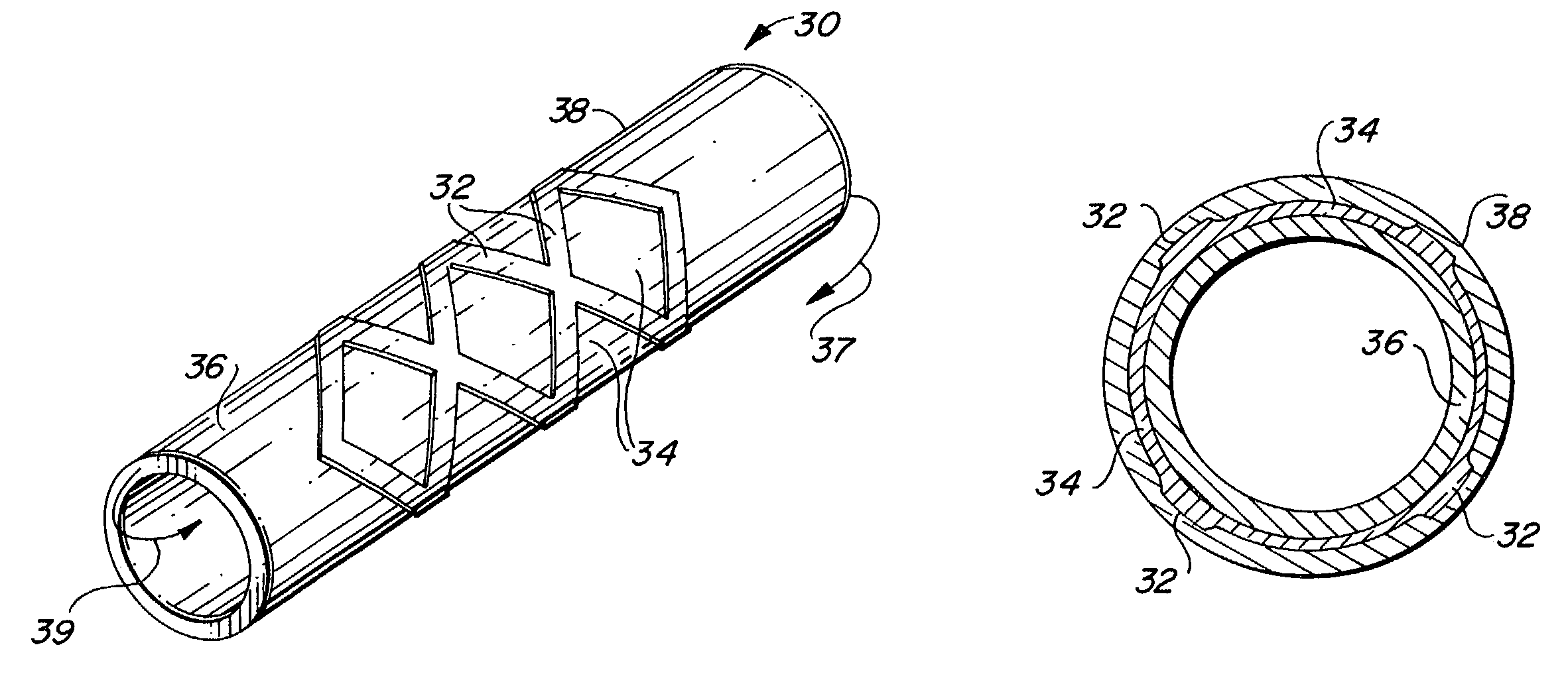
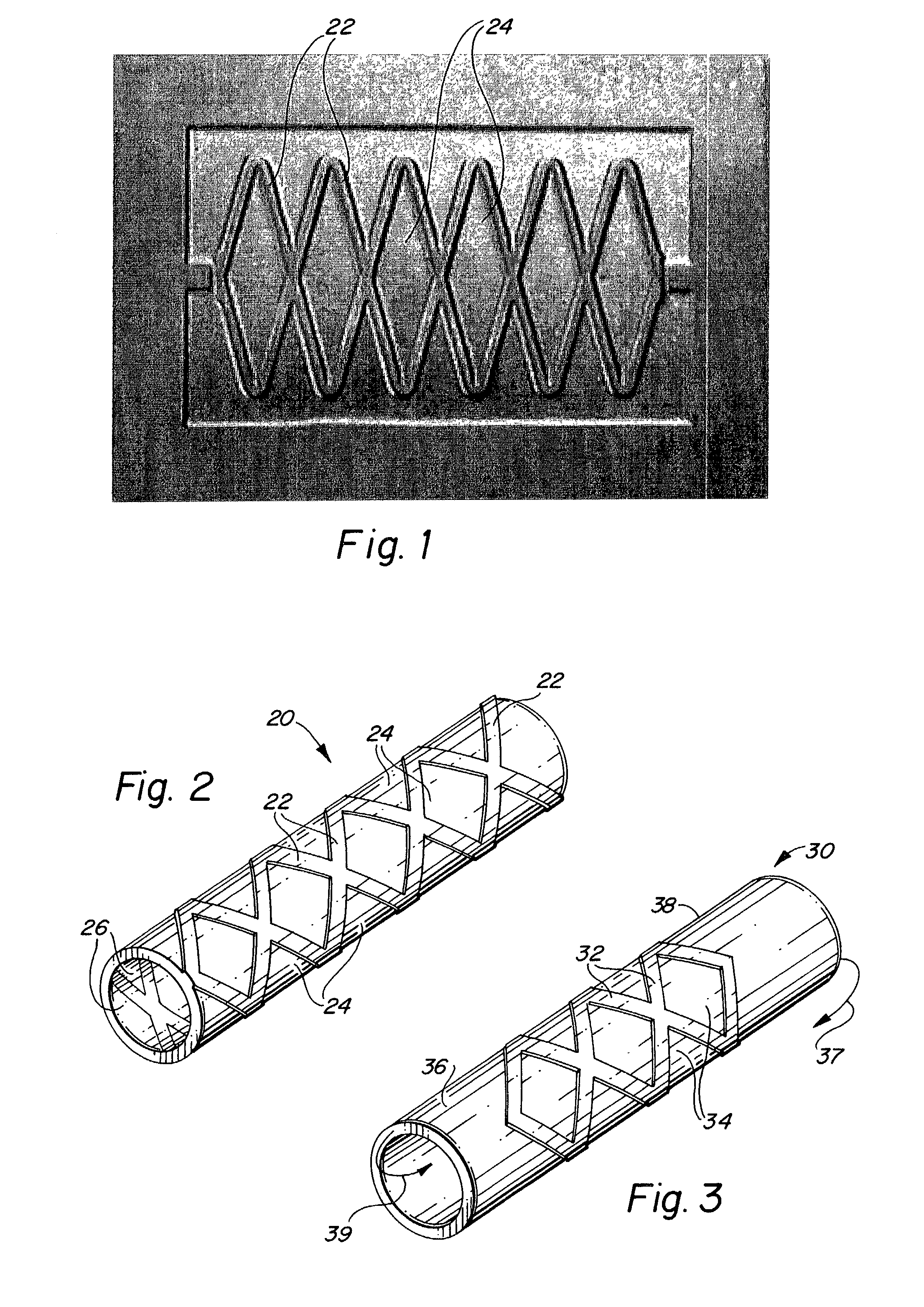
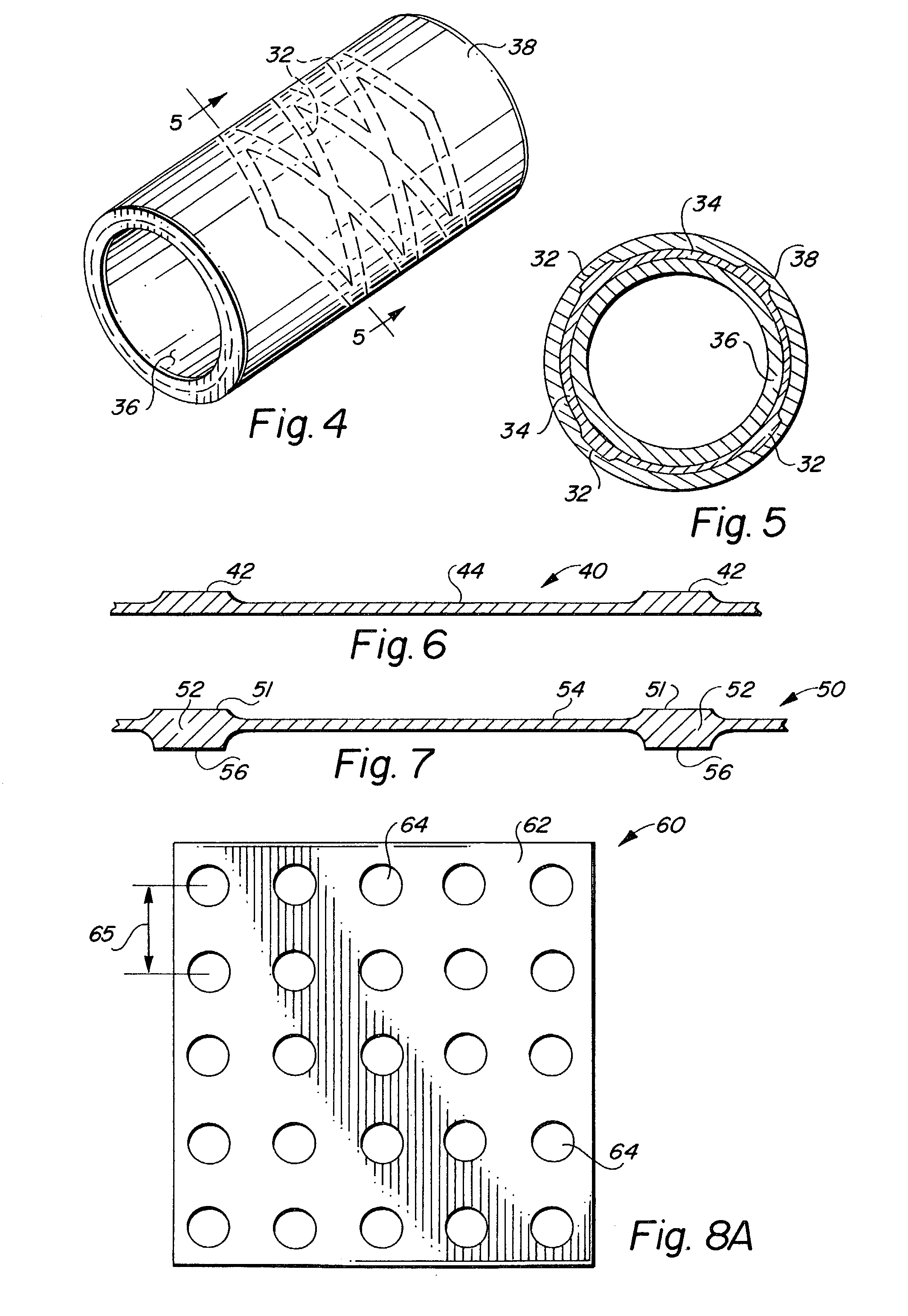
The present invention provides a web-stent device with a plurality of structural members that provide support and a web that extends between the structural members. The device can be used as a stent-graft or a graft alone. The graft can be formed as a thin sheet or tube of biocompatible metal or metal-like materials with patterned openings that allow cellular migration and healing in vivo. The invention also provides a method of fabricating the device and an implantable endoluminal device with a homogeneous material constitution.

Problems solved by technology

While the use of endoluminal stents has successfully decreased the rate of restenosis in angioplasty patients, it has been found that a significant restenosis rate continues to exist even with the use of endoluminal stents.
However, conventional grafts are not a complete solution to enhancing the healing response of the devices.
In practice, a perfectly clean surface is unattainable because of immediate adsorption of airborne species, upon exposure to ambient air, of O, O2, CO2, SO2, NO, hydrocarbons and other more complex reactive molecules.
Unpredictable distribution of inclusions such as those mentioned above provide an unpredictable and uncontrolled heterogeneous surface available for interaction with plasma proteins and cells.
These conditions may vary from optimal attachment force and migration speed to insufficient holding strength to sustain attachment, resulting in cell slough under arterial flow conditions.
These prior art coated stents are susceptible to delaminating and / or cracking of the coating when mechanical stresses of transluminal catheter delivery and / or radial expansion in vivo.
Moreover, because these prior art stents employ coatings applied to stents fabricated in accordance with conventional stent formation techniques, e.g., cold-forming metals, the underlying stent substrate is characterized by uncontrolled heterogeneities on the surface thereof.

Method used


Image

  • Endoluminal implantable stent-grafts
  • Endoluminal implantable stent-grafts
  • Endoluminal implantable stent-grafts

Examples


example 1

Stent Formation By Sputtering

[0068]A ceramic cylindrical substrate is introduced into a deposition chamber with capabilities of glow discharge substrate cleaning and sputter deposition of carbon and stainless steel. The deposition chamber is evacuated to a pressure less than or equal to 2×10⁻⁷ Torr. Pre-cleaning of the substrate is conducted under vacuum by glow discharge. The substrate temperature is controlled to achieve a temperature between about 300 and 1100 degrees Centigrade. A bias voltage between −1000 and +1000 volts is applied to the substrate sufficient to cause energetic species arriving at the surface of the substrate to have hyperthermal energy between 0.1 eV and about 700 eV, preferably between 5-50 eV. The deposition sources are circumferential and are oriented to deposit from the target circumferentially about the substrate.

[0069]During deposition, the deposition pressure is maintained between 0.1 and 10 mTorr. A sacrificial carbon layer of substantially uniform th...

example 2

Stent Formation by Sputtering

[0070]The same operating conditions are followed as in Example 1, except that the substrate is tubular and selected to have a coefficient of thermal expansion different than that of the resultant stent. No intermediate layer of sacrificial carbon is deposited onto the substrate, and the outer surface of the substrate is etched with a pattern of recesses defining a desired stent pattern. The substrate is mounted onto a rotational jig within the deposition chamber and rotated at a uniform rate during deposition. Tantalum is used as the target material and deposited into the recesses of the substrate from a single stationary source. After deposition, the temperature of the substrate and the deposited stent are controlled to impart diametric differential in the substrate and stent and permit removal of the stent from the substrate.

example 3

Stent Formation by Ion Beam-assisted Evaporative Deposition

[0071]A cylindrical substrate is introduced into a deposition chamber that has capabilities of: substrate rotation and precise positioning, glow discharge substrate cleaning, ion beam-assisted evaporative deposition, and cylindrical magnetron sputtering. The deposition sources are (a) dual electron beam evaporative sources placed adjacent to one another at the base of the deposition chamber at a fixed distance from the substrate, these are used with simultaneous argon ion impingement onto the substrate from a controlled ion beam source, and (b) a cylindrical magnetron sputtering source with a carbon target capable of circumferentially coating a carbon sacrificial layer of substantially uniform thickness of between 10 and 200 Angstroms onto the substrate.

[0072]The substrate temperature is controlled to achieve a substrate temperature between about 300 and 1100 degrees Centigrade. The deposition chamber is evacuated to a press...


PUM

PropertyMeasurementUnit
surface areaaaaaaaaaaa
diameteraaaaaaaaaa
radiusaaaaaaaaaa

Abstract

An implantable endoluminal device that is fabricated from materials that present a blood or body fluid and tissue contact surface that has controlled heterogeneities in material constitution. An endoluminal stent-graft and web-stent that is made of an monolithic material deposited into a monolayer and etched into regions of structural members and web regions subtending interstitial regions between the structural members. An endoluminal graft is also provided which is made of a biocompatible metal or metal-like material. The endoluminal stent-graft is characterized by having controlled heterogeneities in the stent material along the blood flow surface of the stent and the method of fabricating the stent using vacuum deposition methods.

Description

CROSS-REFERENCE TO RELATED INVENTIONS[0001]This application is a divisional application of U.S. patent application Ser. No. 09 / 532,164 filed Mar. 20, 2000, now U.S. Pat. No. 6,537,310, which is continuation-in-part of U.S. patent application Ser. No. 09 / 443,929, filed Nov. 19, 1999, which issued as U.S. Pat. No. 6,379,383 on Apr. 30, 2002.BACKGROUND OF THE INVENTION[0002]The present invention pertains generally to implantable medical devices and, more particularly, to implantable medical devices which are capable of being implanted utilizing minimally-invasive delivery techniques. More particularly, the present invention relates to endoluminal grafts, stent-grafts and stent-graft-type devices that are implanted into anatomical passageways using minimally invasive delivery techniques. More specifically, the present invention comprises endoluminal grafts, stent-grafts and stent-graft-type devices that are fabricated entirely of biocompatible metals or of biocompatible materials which ...

Claims


Application Information

Patent Timeline
Patent Type & Authority Patents(United States)
IPC IPC(8): A61F2/06A61F2/82A61L31/00
CPCA61F2/07A61F2/915A61F2/91A61F2/82A61F2002/91541A61F2220/0058A61F2220/0041A61F2220/0075A61F2002/9155A61F2002/072A61F2220/005Y10T29/49936A61F2/90A61L27/3679A61L27/04A61L27/507A61L31/022A61F2/0077A61F2002/0086
Inventor PALMAZ, JULIO C.BOYLE, CHRISTOPHER T.BANAS, CHRISTOPHER E.WISEMAN, ROGER W.MARTON, DENES
Owner VACTRONIX SCI LLC
Learn More