Method for filling a pressure vessel with gas

Inactive Publication Date: 2009-02-17
LAIR LIQUIDE SA POUR LETUDE & LEXPLOITATION DES PROCEDES GEORGES CLAUDE
View PDF14 Cites 9 Cited by
  • Summary
  • Abstract
  • Description
  • Claims
  • Application Information

AI Technical Summary

Benefits of technology

[0026]In the method, the pressure vessel, for example a chamber which is to be filled in a gas generator of an airbag system, is connected to a compressed-gas source for the filling gas. This generally done using a gas conduit. The compressed-gas source is, for example, a compressed-gas container, in particular a compressed-gas cylinder, or a high-pressure gas supply. After the filling chamber has been connected to the compressed-gas source, the walls of the chamber which is to be filled, i.e. of the pressure vessel, are cooled to the filling temperature. The filling temperature is generally below 0° C., preferably below minus 50° C. and particularly preferably below minus 100° C., and in particular at a temperature below minus 150° C. Filling at the boiling temperature of cryogenically liquefied hydrogen (−253° C.), cryogenically liquefied nitrogen (−196° C.), cryogenically liquefied oxygen (−183° C.), cryogenically liquefied argon (−186° C.) or other refrigerants or salt solutions and at the sublimation temperature of, for example, dry ice (−78.5° C.) is advantageous, depending on the type of filling gas and the filling pressure which it is desired to generate. The pressure vessel is preferably cooled to a constant temperature. The cooling is effected for example by means of a refrigeration bath or immersion bath with a cooling liquid (e.g. cryogenically liquefied gases), a cooling block (e.g. a cooled metal block), a cold gas (e.g. using a gas tunnel), cold solid particles (e.g. cooled metal beads, dry ice particles), a cold solid (e.g. dry ice) or a cooling device which can be thermostated. By way of example, the cooling takes place in an immersion bath containing a refrigerant, such as cryogenically liquefied nitrogen (LN2). A refrigeration bath containing a cryogenically liquefied gas or dry ice offers the advantage of good heat transfers and therefore excellent temperature stability.
[0039]Depending on how great a quantity of gas is supplied, it is therefore possible to realize very high storage pressures, in particular even of over 300 bar, in particular over 400 bar, without major technical and energy outlay.
[0047]High efficiency, e.g. in the case of helium, low losses.

Problems solved by technology

The gas generators, which are filled with various gases, present huge technical problems in production, both in terms of their own production and during filling with pressures of up to 1000 bar.
Very expensive and complex piston or diaphragm compressors are required in order to generate the very high pressures.
This leads to high investment costs, high operating and maintenance costs.
In addition, a correspondingly complex and expensive downstream gas supply is required for these pressures.
As pressures increase, it becomes technically more difficult and expensive to achieve fast filling times. There is a direct relationship between filling time and warming during the filling operation, i.e. the more quickly filling takes place, the greater the rise in gas temperature, with the result that this filling pressure has to be increased still further in order to achieve the precise quantity of gas for 15° C. or another defined temperature.
The reproducibility becomes more difficult for the reasons mentioned above and entails complex QA measures, such as for example weighing of the filled vessels for accurate filling quantity determination.
At the same time, a significant rise in scrap rates is expected at higher pressures.
This in turn adversely affects the economics of the entire process and therefore leads to higher production costs.

Method used


Image

  • Method for filling a pressure vessel with gas
  • Method for filling a pressure vessel with gas
  • Method for filling a pressure vessel with gas

Examples


Embodiment Construction

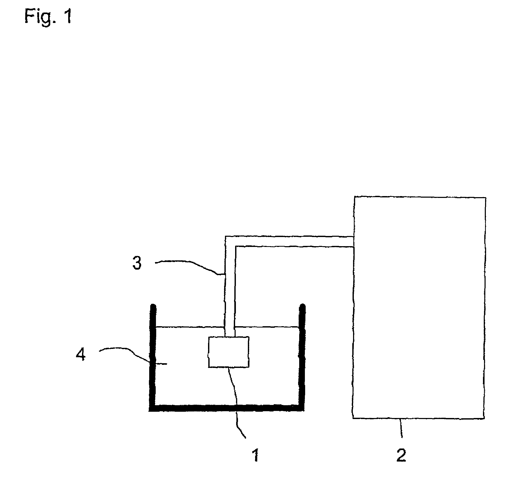
[0055]The filling device shown in FIG. 1 has a pressure vessel 1 which is to be filled, a compressed-gas source 2, e.g. a compressed-gas cylinder (filling pressure for example 300 bar) containing helium or hydrogen with shut-off valve and pressure reducer, a gas connecting conduit 3 and a refrigeration bath 4 containing a cryogenically liquefied gas, such as liquid nitrogen, as refrigerant. The pressure vessel 1 is, for example, part of a gas generator of an airbag system or a gas canister.

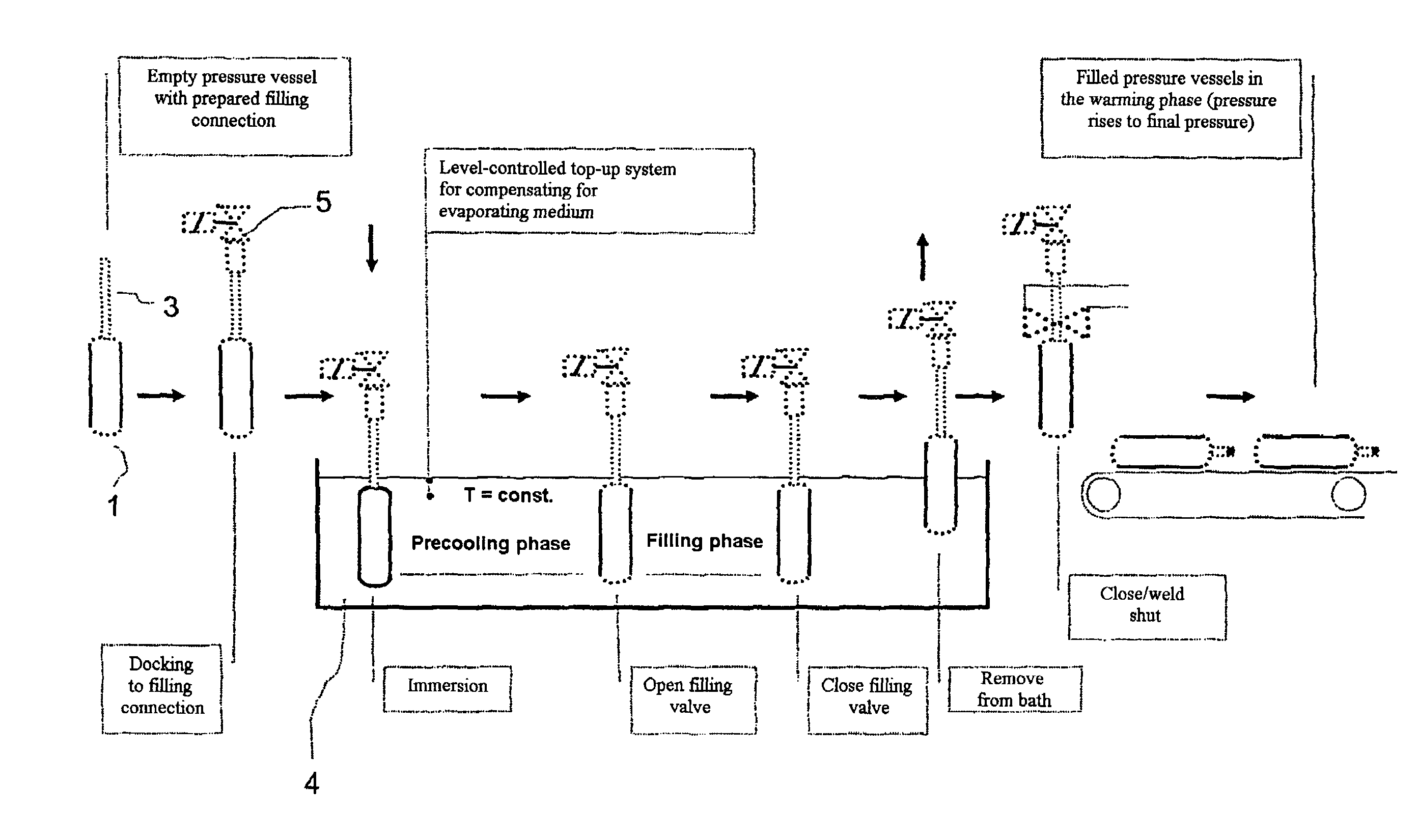
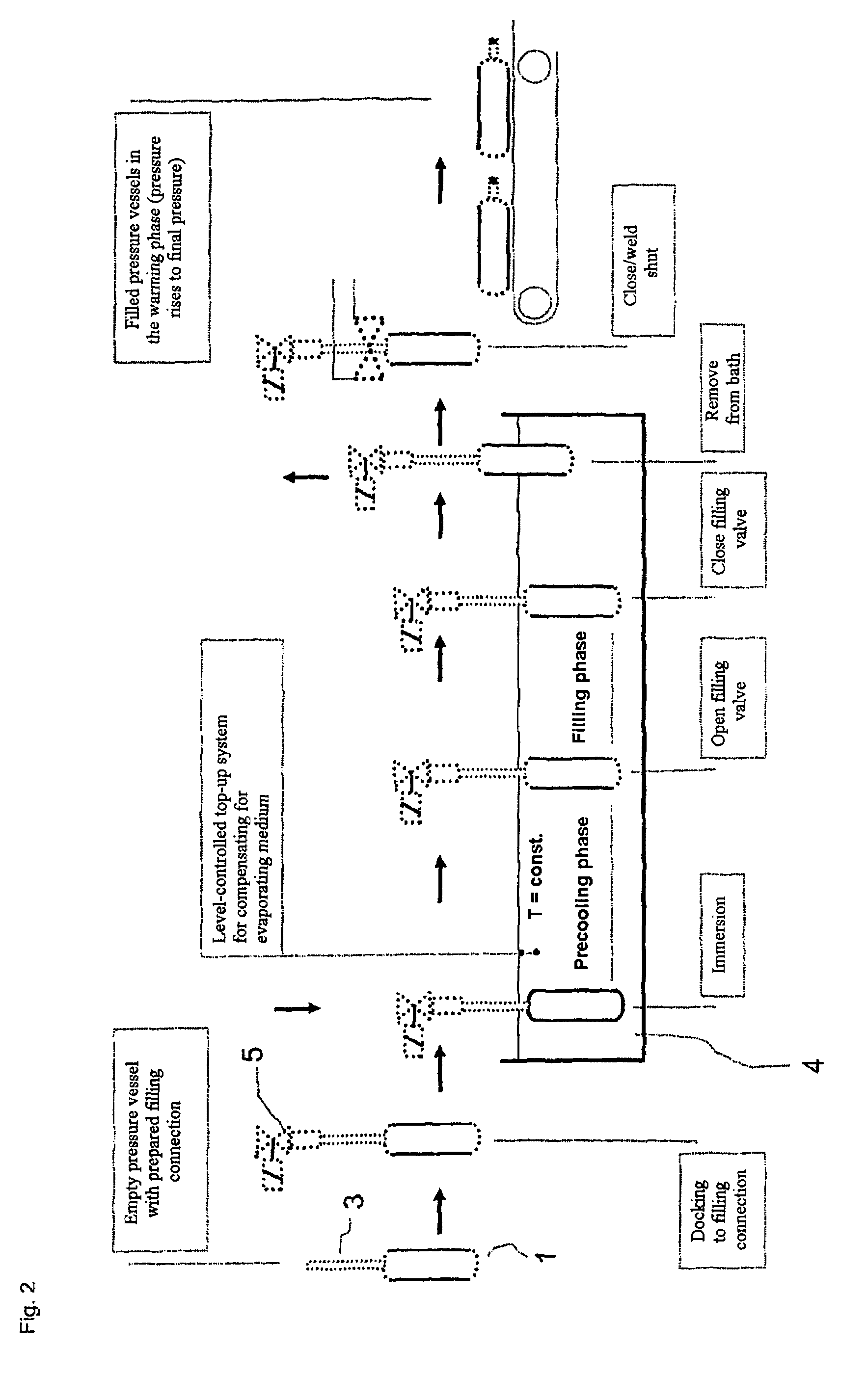
[0056]After the pressure vessel 1 has been immersed in the refrigeration bath 4, the gas which is to be introduced is passed from the compressed-gas source 2 into the pressure vessel 1 by setting a desired pressure (e.g. 90 bar absolute; set at the pressure reducer of the compressed-gas cylinder). The gas, for example helium or hydrogen, quickly adopts the temperature of the surface and therefore the boiling temperature of the refrigerant. In the pressure vessel 1, the gas is cooled to the tempera...


PUM

PropertyMeasurementUnit
Temperatureaaaaaaaaaa
Pressureaaaaaaaaaa

Abstract

A method for filling a pressure vessel, for example an airbag system, with a gas or gas mixture. The filling is accomplished by cooling a pressure vessel, filling said vessel with at least one type of gas at a temperature which is higher than the boiling point thereof and closing the cold vessel. A pressure is produced in the filled and closed vessel by heating said vessel at an ambient temperature.

Description

BACKGROUND OF THE INVENTION[0001]1. Field of the Invention[0002]The invention relates to a method for filling pressure vessels, in particular pressure vessels in airbag systems, with gas.[0003]2. Description of the Related Art[0004]Airbags in vehicles are increasingly using new gas generators which inflate the airbag within a few milliseconds in the event of an accident. At present, three types of gas generators are in use:[0005]chemical generators, in which the gas is generated by the reaction of a chemical solid with ambient air;[0006]what are known as hybrid generators, which comprise a combination of solid fuel and compressed-gas packing; and[0007]pure gas generators with a high-pressure gas storage system with pressures of up to 700 bar at 15° C.[0008]The gas generators, which are filled with various gases, present huge technical problems in production, both in terms of their own production and during filling with pressures of up to 1000 bar. These pressures are required in par...

Claims


Application Information

Patent Timeline
IPC IPC(8): B65B1/04F17C5/04F17C5/06F17C13/02
CPCF17C5/04F17C5/06F17C2201/0104F17C2201/058F17C2203/0617F17C2205/0311F17C2209/221F17C2221/011F17C2221/012F17C2221/014F17C2221/016F17C2221/017F17C2223/0161F17C2223/035F17C2223/046F17C2225/0123F17C2225/036F17C2227/0302F17C2227/0311F17C2227/0383Y02E60/321F17C2270/059Y10T137/6416Y02E60/32
Inventor GRABHORN, HERMANNKLEBE, ULRICHMICHEL, FRIEDEL
Owner LAIR LIQUIDE SA POUR LETUDE & LEXPLOITATION DES PROCEDES GEORGES CLAUDE
Why Eureka
Try Eureka