
Low dead volume extraction column device

a column device and low-desty technology, applied in sedimentation separation, biological material analysis, chemical/physical processes, etc., can solve the problems of difficult application of the packed-bed approach, limited quantification and/or enrichment of samples, complex processing of protein samples,

Active Publication Date: 2009-01-27
PHYNEXUS
View PDF38 Cites 37 Cited by
  • Summary
  • Abstract
  • Description
  • Claims
  • Application Information

AI Technical Summary

Benefits of technology

"This patent describes a column device for capturing components from a fluid sample. The column has a body with an upper and lower end, with a membrane screen at the top and bottom. The column can be attached to a pump for aspirating and discharging fluid. The invention also provides a method for extracting analytes from a sample solution using the column. The technical effects of this invention include a low dead volume extraction column with improved pore volume and reduced pore size, as well as a method for extracting analytes from a sample solution with improved efficiency."

Problems solved by technology

Protein sample processing is a complex problem within proteomics.
Due to the very nature of a conventional packed-bed approach, it is limited with respect to reliable quantification and / or enrichment of sample.
A packed-bed approach is extremely difficult to apply in a manner that is both cost-effective and reliable.
It cannot be effectively applied to a microscale process level.
Moreover, packed columns have extensive carry-over from sample to sample, are expensive to manufacture, and may be difficult to multiplex (extract multiple samples simultaneously).
Proteins may be irreversibly adsorbed to the extraction phase or may be trapped by frits and other “dead zones” within the column making recovery of the proteins incomplete.
Other drawbacks include losses of materials due to unswept volumes leading to low recoveries and irreproducibility of results; dilution of materials due to large elution volumes applied in an attempt to minimize these selfsame unswept volumes; depending on implementation, requirements often to adhere to a flow “directionality” introducing limitations on full integration of sample processing; manufacturing difficulties and costs for micro- or nanoscale volume systems; and porosity of construction materials used in commercially available systems that cause severe loss of biomaterials.
Conventional frits, porous discs used to contain the column beds, have significant dead volume.
This leads to significant sample loss when very small sample volumes are separated.
However, the plugs also entrap excess liquid thereby creating dead space or volume (i.e., space not occupied by media or polymer that can lead to poor sample recovery, contamination such as by sample carry-over, etc.).
Current available methods are not well suited for the separation and recovery of very small volumes in the low microliter range.
Also, since the volume of the filter is often as large as the volume of the micro volume sample itself, the extraction or separation process or chromatography process is adversely affected due to the large volume of filter material through which the sample must pass.
In addition, the adsorption of biomolecules can be a problem.
Since the concentration of biomolecules in micro volume samples is so small, the adsorption of biomolecules on the filter can result in significant loss of the total sample mass.
The filter material may also absorb proteins or biomolecules from the sample, resulting in lower than desirable sample recovery.
Also, the filter material may behave differently in different elution media, subsequently interfering with both the quality of the separation process and the volume of the sample retained.
Conventional methods and devices for sample preparation are not practical for handling the “microseparation” of such small sample volumes.
However, these procedures cannot be used with extremely small liquid delivery devices such as conventional pipette tips, as there is no practical way to load either the plug or the particles to obtain a micro-adsorptive device that contains 20 milligrams or less of adsorbent, the amount suitable for use with the aforementioned extremely small sample loads.

Method used


Image

  • Low dead volume extraction column device
  • Low dead volume extraction column device
  • Low dead volume extraction column device

Examples


example 1

Preparation of an Extraction Column Body from Pipette Tips

[0189]Two 1000 μL polypropylene pipette tips of the design shown in FIG. 6 (VWR, Brisbane, Calif., PN 53508-987) were used to construct one extraction column. In this example, two extraction columns were constructed: a 10 μL bed volume and 20 μL bed volume. To construct a column, various components were made by inserting the tips into several custom aluminum cutting tools and cutting the excess material extending out of the tool with a razor blade to give specified column lengths and diameters.

[0190]Referring to FIG. 7, the first cut 92 was made to the tip 92 of a pipette tube 90 to form a 1.25 mm inside diameter hole 94 on the lower column body, and a second cut 96 was made to form a lower column body segment 98 having a length of 15.0 mm.

[0191]Referring to FIG. 8, a cut 102 was made to the separate pipette tip 100 to form the upper column body 104. To make a 10 μL bed volume column, the cut 102 was made to provide a tip 106...

example 2

Preparation of SEPHAROSEProtein G and MEP HYPERCEL™ Extraction Columns

[0194]Referring to FIG. 9, a suspension of Protein G SEPHAROSE™ 4 Fast Flow, 45-165 μm particle size, (Amersham Biosciences, Piscataway, N.J., PN 17-0618-01) in water / ethanol was prepared, and an appropriate amount of material 114 was pipetted into the lower column body 98.

[0195]Referring to FIG. 10, the upper column body 104 was pushed into the lower column body 98 so that no dead space was left at the top of the bed 114, that is, at the top of the column bed. Care was taken so that a seal was formed between the upper and lower column bodies 104 and 98 while retaining the integrity of the membrane screen bonding to the column bodies.

[0196]Several tips of 10 μL and 20 μL bed volumes were prepared. Several MEP (Mercapto-Ethyl-Pyridine) HYPERCEL™ (Ciphergen, Fremont, Calif., PN 12035-010) extraction columns were prepared using the same procedure. MEP HyperCel™ resin is a sorbent, 80-100 μm particle size, designed ...

example 3

Purification of Anti-leptin Monoclonal Antibody IgG with 10 μL and 20 μL Bed Volume Protein G SEPHAROSE™ Extraction Columns

[0197]A Protein G SEPHAROSE™ 4 Fast Flow (Amersham Biosciences, Piscataway, N.J., PN 17-0618-01) extraction column was prepared as described in Example 2.

[0198]Five hundred μL serum-free media (HTS Biosystems, Hopkinton, Mass.) containing IgG (HTS Biosystems, Hopkinton, Mass.) of interest was combined with 500 μL standard PBS buffer. The resulting 1 mL sample was pulled into the pipette tip, through the Protein G packed bed at a flow rate of approximately 1 mL / min) or roughly 15 cm / min). The sample was then pushed out to waste at the same approximate flow rate. Extraneous buffer was removed from the bed by pulling 1 mL of deionized water into the pipette column at about 1 mL / min and pushing it out at about 1 mL / min. The water was pushed out as much as possible to achieve as dry of a column bed as is possible. The IgG was eluted from the column bed by drawing up ...


PUM

PropertyMeasurementUnit
thickaaaaaaaaaa
thickaaaaaaaaaa
bed volumeaaaaaaaaaa

Abstract

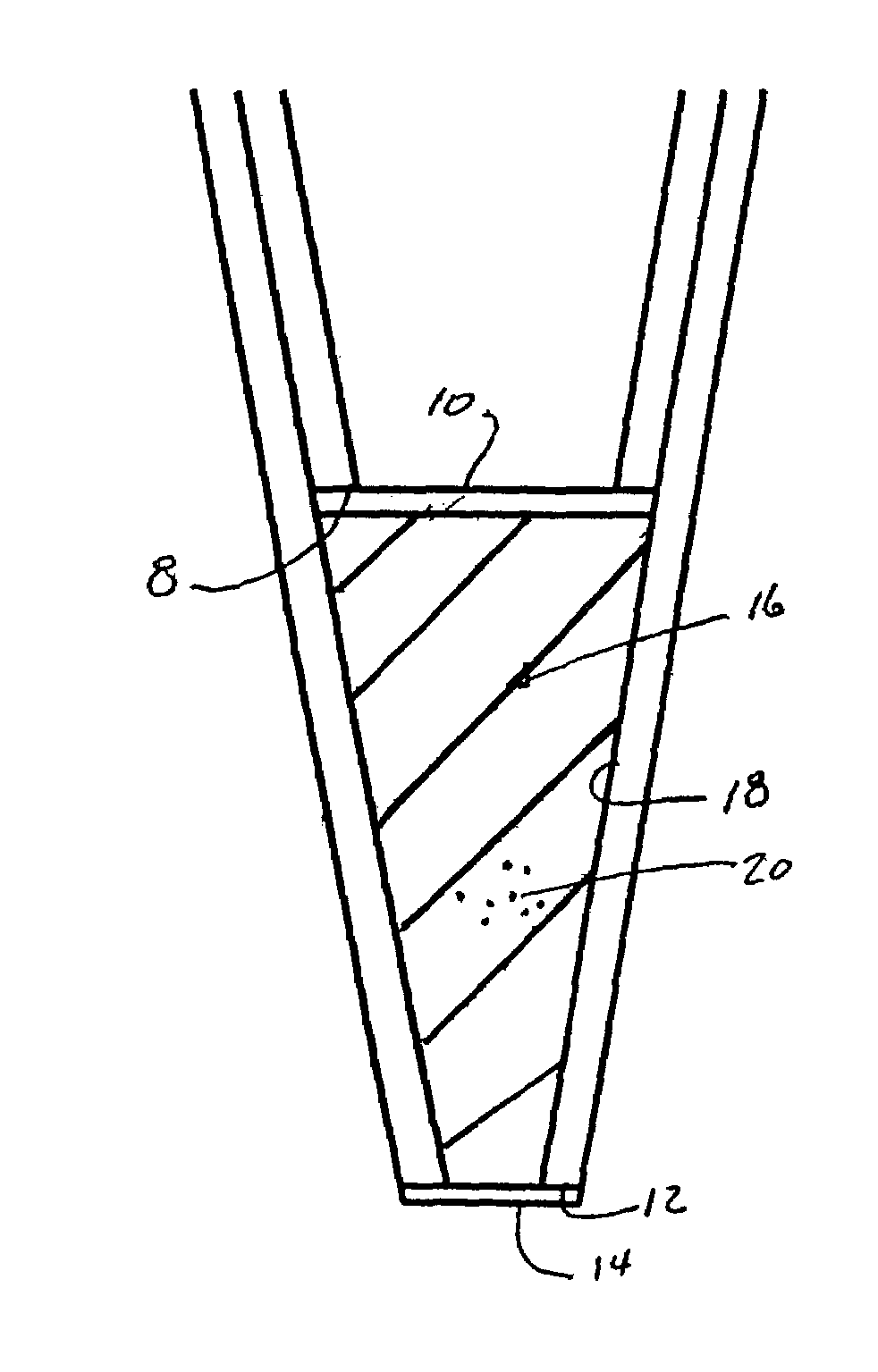
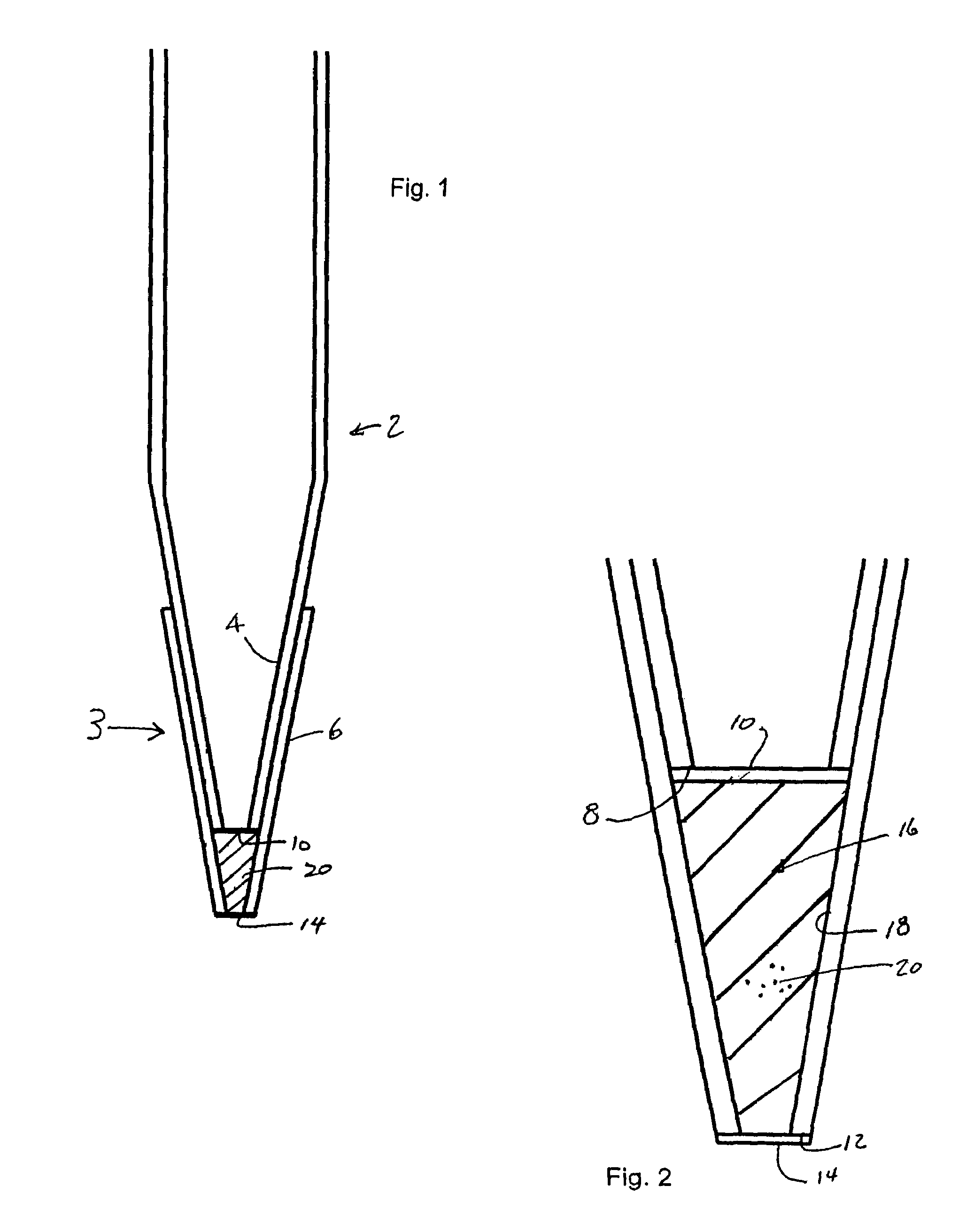
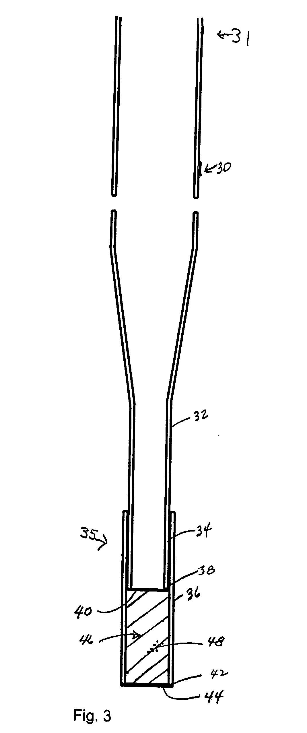
The invention provides extraction columns for the purification of an analyte (e.g., a biological macromolecule, such as a peptide, protein or nucleic acid) from a sample solution, as well as methods for making and using such columns. The invention is characterized by the use of low dead volume columns, which is achieved in part by the use of low pore volume frits (e.g., membrane screens) to contain a bed of extraction media in the column. Low dead volume facilitates the elution of the captured analyte into a very small volume of desorption solution, allowing for the preparation of low volume samples containing relatively high concentrations of analyte.

Description

CROSS-REFERENCE TO RELATED APPLICATIONS[0001]This application claims priority to and benefit of U.S. Provisional Patent Application Serial No. 60 / 396,595, filed Jul. 15, 2002 and U.S. Provisional Patent Application Serial No. 60 / 465,606, filed Apr. 25, 2003, the disclosures of which are incorporated herein by reference in its entirety for all purposes.FIELD OF THE INVENTION[0002]This invention relates to a device and method for the capture of analytes by solid phase extraction with a column device and collection of the analytes into a controlled volume of solvent. The analytes can include biomolecules, particularly biological macromolecules such as proteins and peptides. The device and method of this invention are particularly useful in proteomics for sample preparation and analysis with analytical technologies employing biochips, mass spectrometry and other instrumentation.BACKGROUND OF THE INVENTION[0003]Proteomics can be defined as the comprehensive study of proteins and their fu...

Claims


Application Information

Patent Timeline
Patent Type & Authority Patents(United States)
IPC IPC(8): G01N1/18B01D15/08B01L11/00B01L3/02C02F1/28B01D15/32B01D15/38B01J20/285B01J20/291B01L99/00G01N30/00G01N30/60G01N35/10
CPCB01J20/285B01J20/291B01L3/0275B82Y30/00B01D15/325Y10T436/255B01D15/3804B01J2220/64B01L2200/0631G01N30/6004G01N2030/009G01N2035/1039B01D15/327G01N2030/525
Inventor GJERDE, DOUGLAS T.HANNA, CHRISTOPHER T.
Owner PHYNEXUS
Learn More