
Optical recording medium

a technology of optical recording medium and optical recording medium, which is applied in the field of optical recording medium, can solve the problems of uncured spin-coating layer near the edge of the center cap that is prone to non-uniformity, and the axial runout of the optical recording medium occurs, and achieves the effect of reducing the axial runout during high-speed rotation and high-reliability recording

Inactive Publication Date: 2009-01-13
CMC MAGNETICS CORPORATION
View PDF12 Cites 0 Cited by
  • Summary
  • Abstract
  • Description
  • Claims
  • Application Information

AI Technical Summary

Benefits of technology

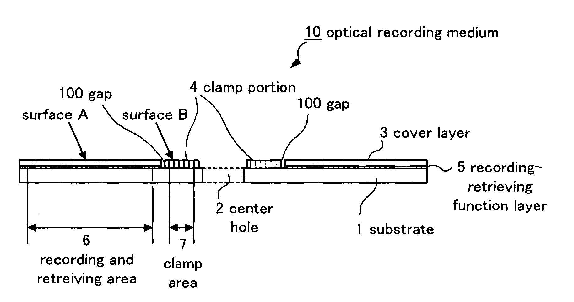
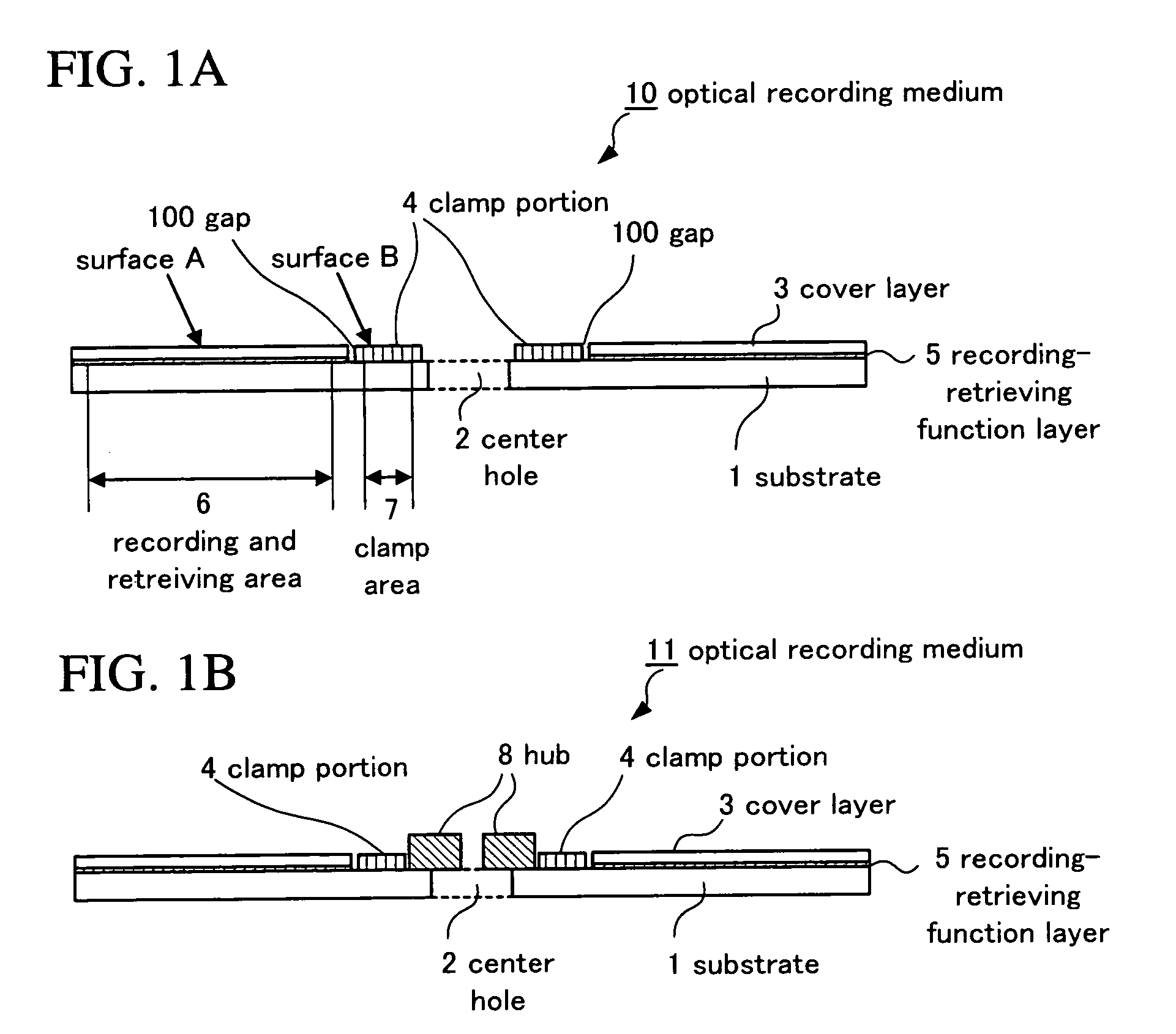
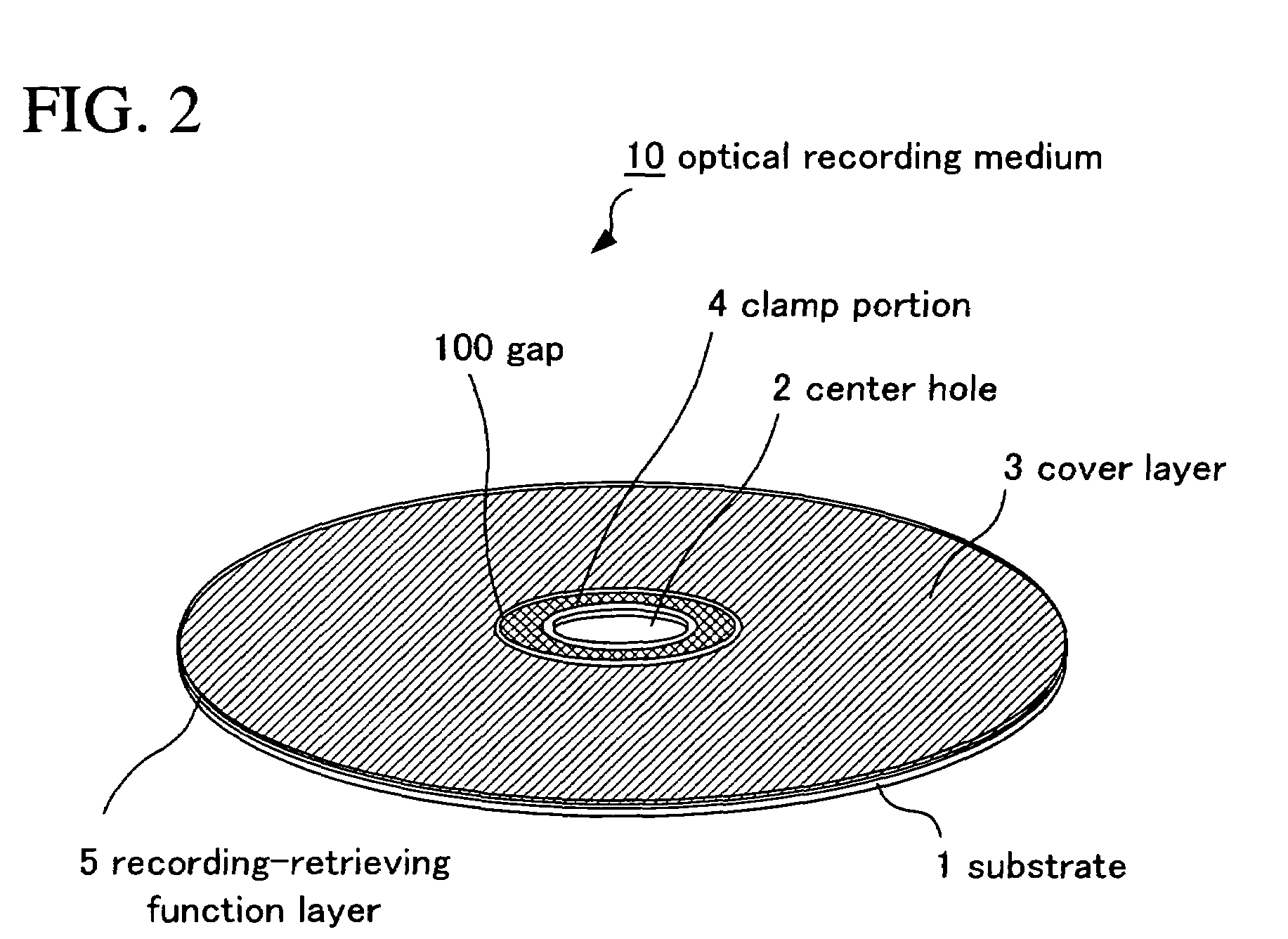
"The present invention aims to provide an optical recording medium with low axial runout during high-speed rotation and reliable recording and retrieving of information signals. The invention achieves this by providing a separate clamp portion from the cover layer, which improves the surface flatness of the recording-retrieving function layer and reduces variations in the distance between the medium and the objective lens. The clamp portion is formed of thermoplastic resin and is attached to the substrate or the recording-retrieving function layer. The cover layer is formed of photocurable resin and can allow light to pass through it. The invention also provides a method of manufacturing the optical recording medium with the clamp portion."

Problems solved by technology

This newly causes a problem.
Specifically, if the optical recording medium is rotated at high speed while being held and fixed in a rotating device, the axial runout of the optical recording medium occurs.
Due to the occurrence of the axial runout, recording and retrieving are prone to fail.
Furthermore, since the working distance is small, the objective lens may come into contact with the surface of the optical recording medium to scratch the surface of the optical recording medium or the objective lens in the case where the axial runout is large.
Further, in the case where the optically transparent layer (cover layer) is formed by spin coating, there is a following problem: when a center cap used for obtaining the uniformity of the coating film thickness is removed after the completion of spin coating, uncured spin-coating layer near the edge of the center cap is prone to be made nonuniform, and therefore the flatness of the clamp portion is lowered.

Method used


Image

  • Optical recording medium
  • Optical recording medium
  • Optical recording medium

Examples


example 1

[0106]The optical recording medium 10 in which a clamp portion as separate entity from a cover layer was provided as shown in FIG. 1A was prepared in accordance with the following procedure.

Step of Forming Substrate

[0107]A polycarbonate substrate 1 which had a diameter of 120 mm and a thickness of 1.1 mm and in which a groove for tracking was previously formed at a track pitch of 0.32 μm, was prepared. It is noted that the groove width was approximately 50% of the track pitch, and that the groove depth was 20 to 30 nm.

Step of Forming Recording-Retrieving Function Layer

[0108]Next, a reflecting layer, a dielectric layer 1, a recording layer, and a dielectric layer 2, which are described below, were stacked in this order on the substrate 1 by sputtering to form a recording-retrieving function layer 5, and thus a rewritable optical recording medium was formed.

[0109]Reflecting layer: having a thickness of 100 nm, formed by use of Ag alloy.

[0110]Dielectric layer 1: transparent, having a t...

example 2

[0144]An optical recording medium having a form different from that in the case of Example 1 was prepared in accordance with the following procedure.

[0145]FIG. 8 is a view for explaining a third embodiment of an optical recording medium to which the present embodiment is applied. In FIG. 8, an optical recording medium 800 provided with a clamp portion as a separate entity from a cover layer is shown. The same components as those of the aforementioned optical recording medium 10 shown in FIG. 1A are denoted by the same reference numerals. The optical recording medium 800 comprises: two substrates of a substrate A 204 and a substrate B 205 in which center holes 2 are opened at the respective centers; a recording-retrieving function layer A 200 and a recording-retrieving function layer B 201 which are respectively formed on the substrate A 204 and the substrate B 205 and in which recording and / or retrieving of information signals is performed by use of irradiated light; a cover layer A...


PUM

PropertyMeasurementUnit
step heightaaaaaaaaaa
distanceaaaaaaaaaa
thicknessaaaaaaaaaa

Abstract

An optical recording medium includes a plane ring-shaped substrate in which a center hole is opened at the center thereof, a recording-retrieving function layer and a cover layer each having an outer diameter approximately equal to that of the substrate and an inner diameter larger than an outer diameter of the center hole, are stacked on the substrate, and as a separate entity from the cover layer, a clamp portion which is for holding and fixing the substrate and which has an outer diameter smaller than inner diameters of the recording-retrieving function layer and the cover layer, is provided around the center hole in a region where the cover layer is not formed.

Description

BACKGROUND OF THE INVENTION[0001]1. Field of the Invention[0002]The present invention relates to an optical recording medium. More specifically, the present invention relates to an optical recording medium in which highly reliable recording and / or retrieving of optical information signals is performed.[0003]2. Description of the Related Art[0004]In recent years, in order to cope with the trend toward higher recording density required for optical recording media (hereinafter also simply referred to as “disks” or “optical disks”) technology for reducing the diameter of the spot of recording or retrieving light is being developed. Specifically, in the above-described technology, the diameter of the spot of recording or retrieving light is reduced by increasing the numerical aperture (NA) of an objective lens of an optical pickup. The objective lens is used for irradiating recording or retrieving light.[0005]Moreover, in addition to increasing the NA of the objective lens, a study to th...

Claims


Application Information

Patent Timeline
Patent Type & Authority Patents(United States)
IPC IPC(8): G11B7/24G11B7/26G11B23/00
CPCG11B7/24097G11B7/266G11B23/0035
Inventor KANEHIRA, JUNISHIZAKI, OSAMU
Owner CMC MAGNETICS CORPORATION
Learn More