Optical recording medium and method of manufacturing the same
a technology of optical recording medium and manufacturing method, which is applied in the field of optical recording medium, can solve the problems of uncured spin-coating layer near the edge of the center cap that is prone to non-uniformity, and the axial runout of the optical recording medium occurs, and achieves the effect of reducing the axial runout during high-speed rotation and high-reliability recording
- Summary
- Abstract
- Description
- Claims
- Application Information
AI Technical Summary
Benefits of technology
Problems solved by technology
Method used
Image
Examples
second embodiment
Next, an optical recording medium to which the present embodiment is applied will be described.
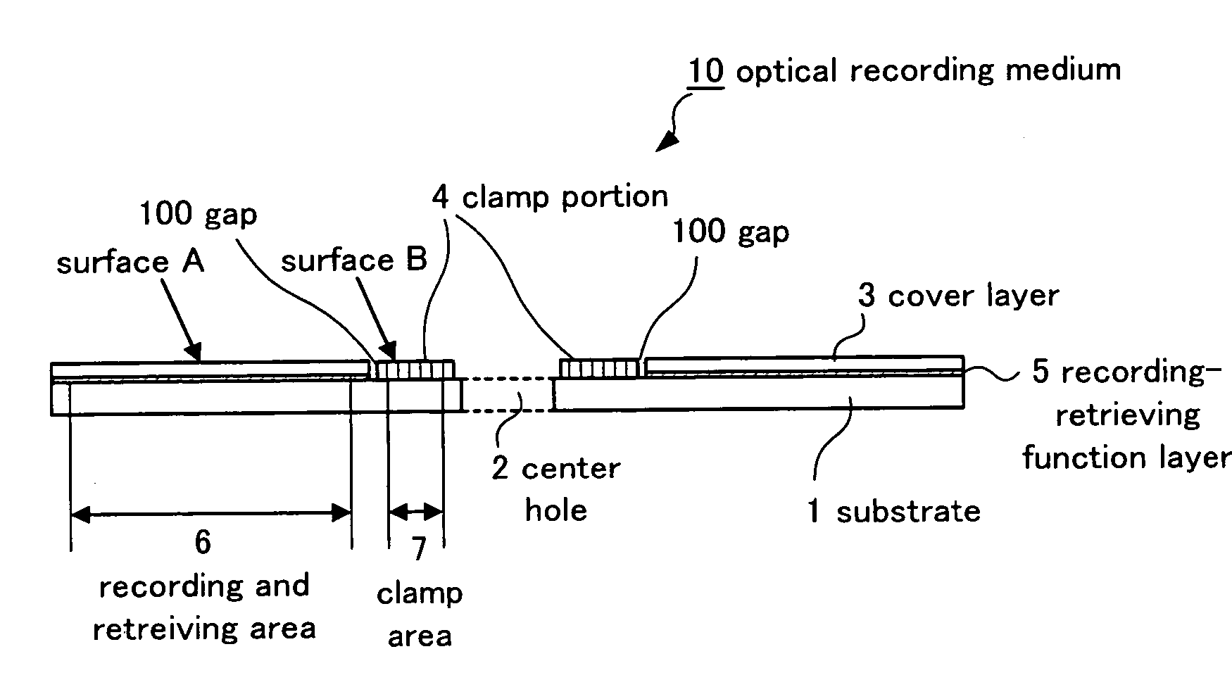
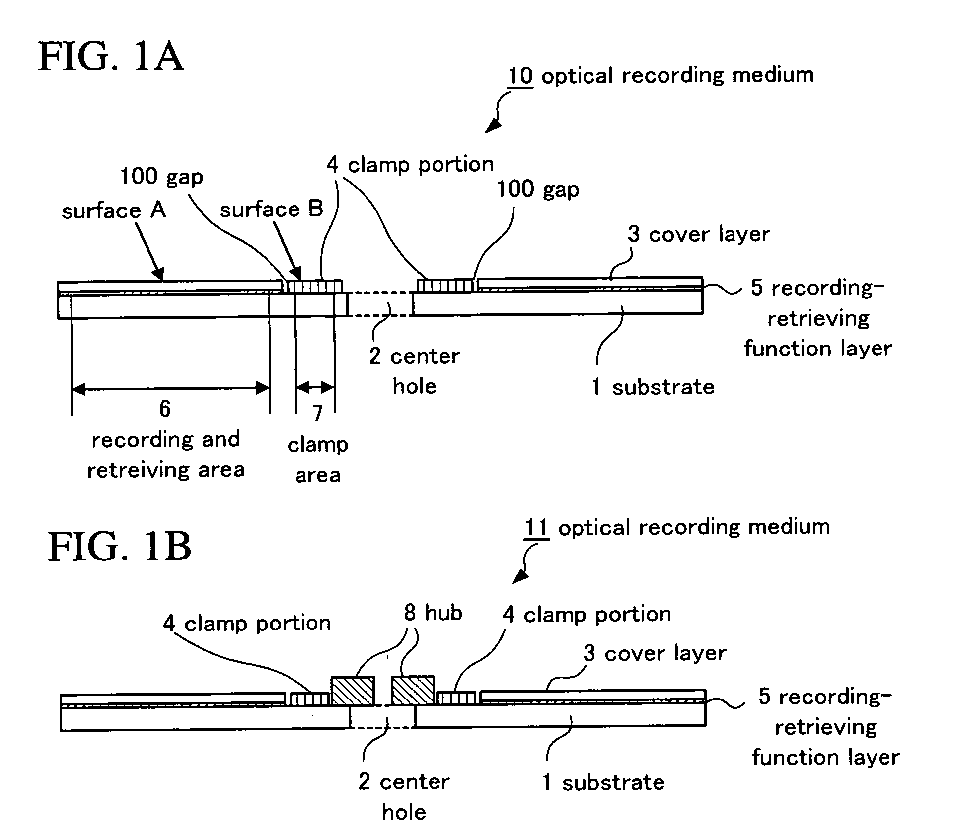
FIG. 1B is a view for explaining the second embodiment of the optical recording medium to which the present embodiment is applied. The optical recording medium 11 shown in FIG. 1B is provided with a ring-shaped hub 8 in such a manner that the center of the hub 8 is approximately aligned to the center of the center hole 2 opened at the center of the substrate 1. Other components of the optical recording medium 11 are the same as those of the optical recording medium 10 shown in FIG. 1A, and therefore will not be further described. The hub 8 is generally used for precisely aligning the center of an optical recording medium when the substrate 1 is holded in a rotating device. For example, as a system like MO disk, such as a system in which a disk is frequently attached and detached is used, or a reliable system in which decentering due to chucking shift is reduced is used, it is preferable to...
example 1
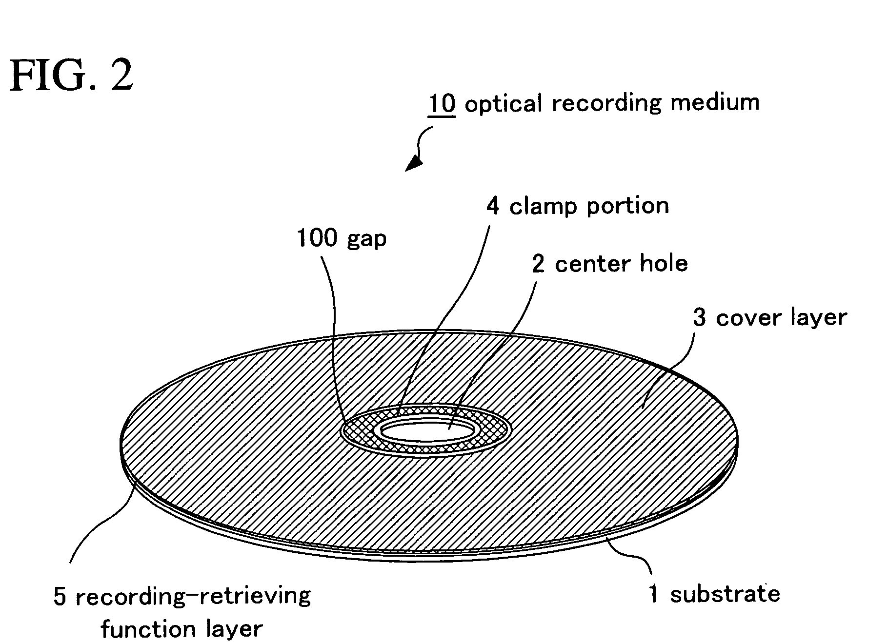
The optical recording medium 10 in which a clamp portion as separate entity from a cover layer was provided as shown in FIG. 1A was prepared in accordance with the following procedure.
(Step of Forming Substrate)
A polycarbonate substrate 1 which had a diameter of 120 mm and a thickness of 1.1 mm and in which a groove for tracking was previously formed at a track pitch of 0.32 μm, was prepared. It is noted that the groove width was approximately 50% of the track pitch, and that the groove depth was 20 to 30 nm.
(Step of Forming Recording-Retrieving Function Layer)
Next, a reflecting layer, a dielectric layer 1, a recording layer, and a dielectric layer 2, which are described below, were stacked in this order on the substrate 1 by sputtering to form a recording-retrieving function layer 5, and thus a rewritable optical recording medium was formed.
Reflecting layer: having a thickness of 100 nm, formed by use of Ag alloy.
Dielectric layer 1: transparent, having a thickness of 1...
example 2
An optical recording medium having a form different from that in the case of Example 1 was prepared in accordance with the following procedure.
FIG. 8 is a view for explaining a third embodiment of an optical recording medium to which the present embodiment is applied. In FIG. 8, an optical recording medium 800 provided with a clamp portion as a separate entity from a cover layer is shown. The same components as those of the aforementioned optical recording medium 10 shown in FIG. 1A are denoted by the same reference numerals. The optical recording medium 800 comprises: two substrates of a substrate A 204 and a substrate B 205 in which center holes 2 are opened at the respective centers; a recording-retrieving function layer A 200 and a recording-retrieving function layer B 201 which are respectively formed on the substrate A 204 and the substrate B 205 and in which recording and / or retrieving of information signals is performed by use of irradiated light; a cover layer A 202 and a...
PUM
| Property | Measurement | Unit |
|---|---|---|
| step height | aaaaa | aaaaa |
| distance | aaaaa | aaaaa |
| thickness | aaaaa | aaaaa |
Abstract
Description
Claims
Application Information
 - R&D
- Intellectual Property
- Life Sciences
- Materials
- Tech Scout
- Unparalleled Data Quality
- Higher Quality Content
- 60% Fewer Hallucinations
Browse by: Latest US Patents, China's latest patents, Technical Efficacy Thesaurus, Application Domain, Technology Topic, Popular Technical Reports.
© 2025 PatSnap. All rights reserved.Legal|Privacy policy|Modern Slavery Act Transparency Statement|Sitemap|About US| Contact US: help@patsnap.com


