Method and apparatus for analyzing optical characteristics of optical medium and method for production monitoring
a technology of optical characteristics and analysis methods, applied in the direction of optical radiation measurement, instruments, polarisation-affecting properties, etc., can solve the problems of insufficient description of actual film properties by models such as simple uniaxial models or biaxial models, and difficulty in accurately expressing the internal micro-structure of actual optical films, etc., to achieve the effect of improving the production stability of optical mediums
- Summary
- Abstract
- Description
- Claims
- Application Information
AI Technical Summary
Benefits of technology
Problems solved by technology
Method used
Image
Examples
example 1
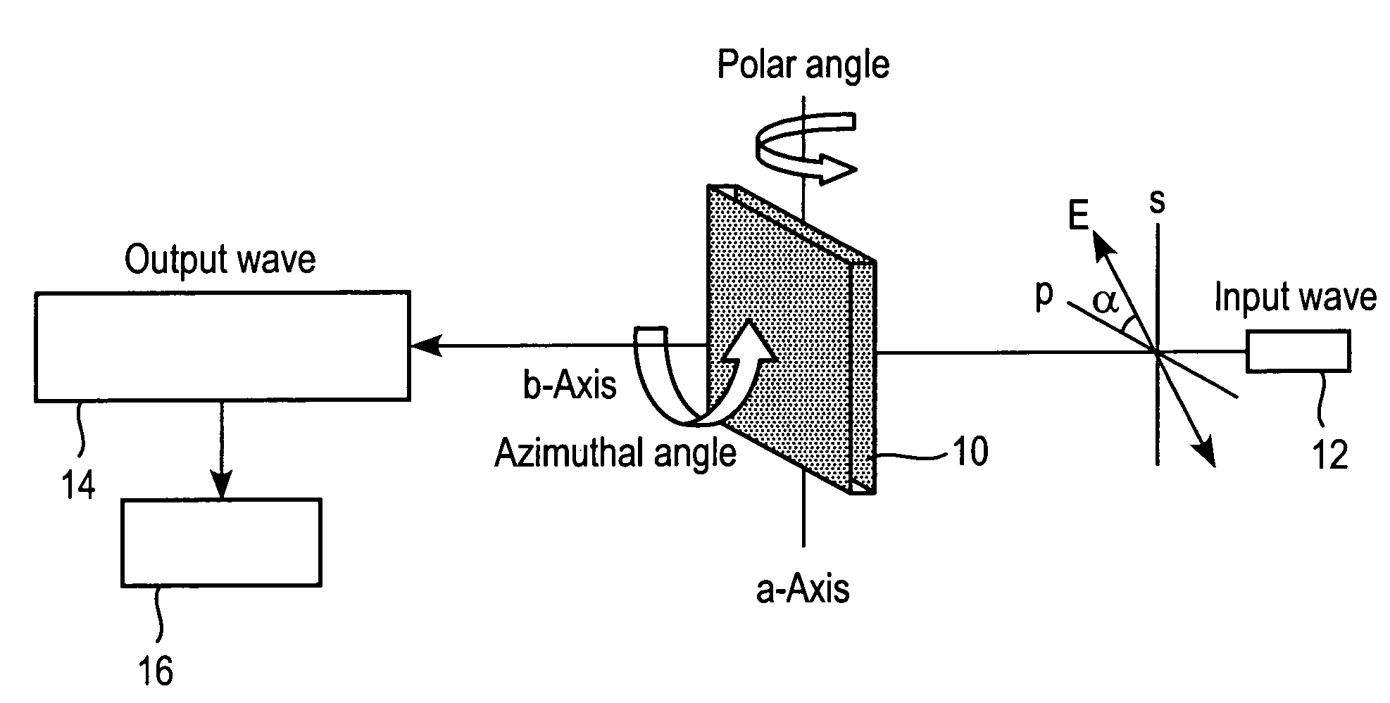
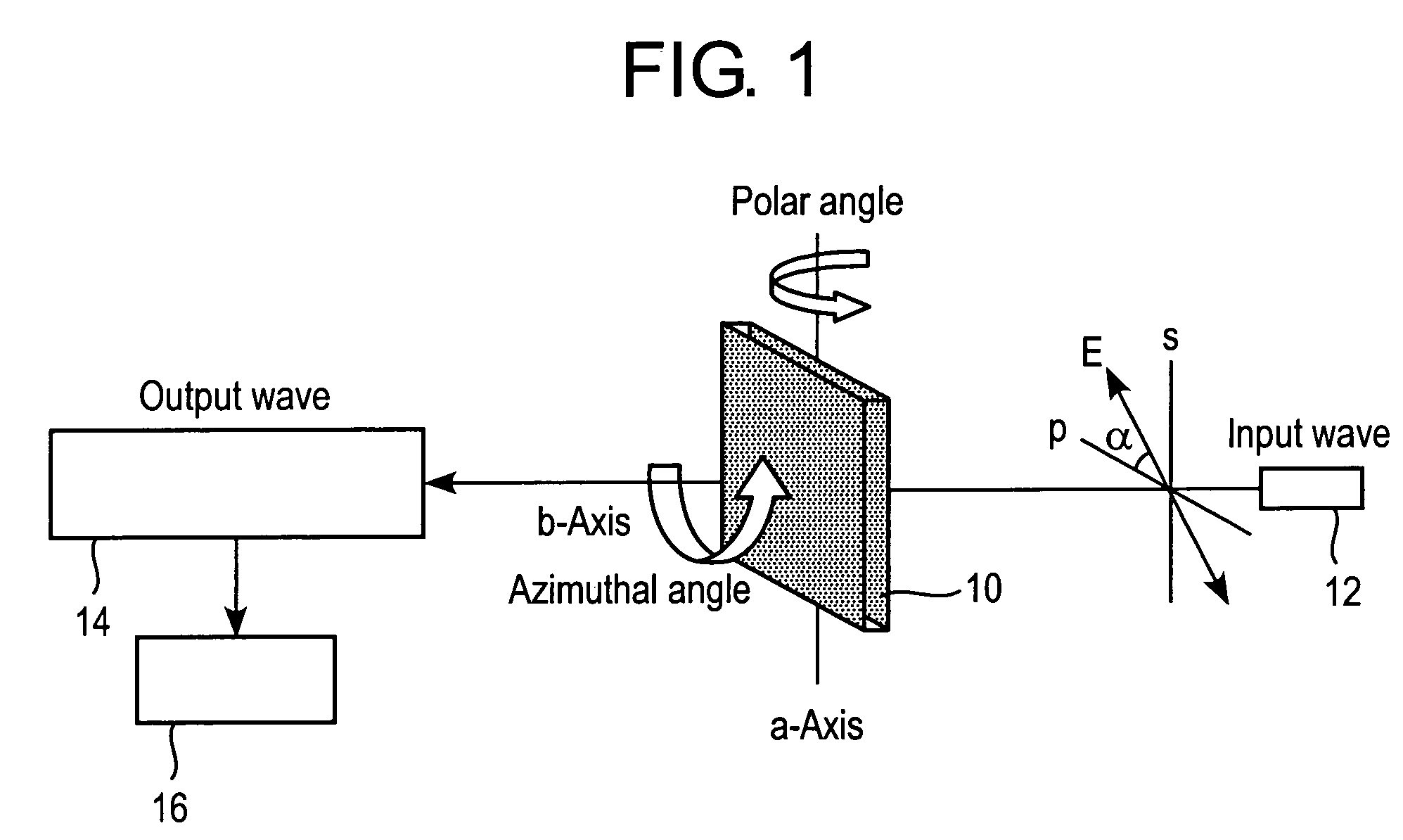
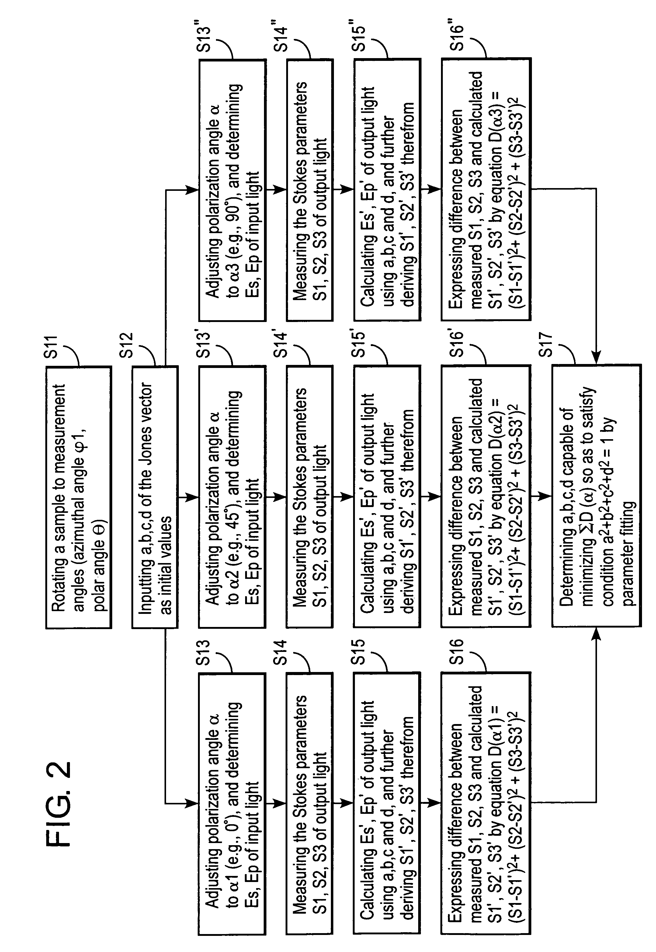
[0080]The Jones matrix of a polymer film was measured using an analyzer configured as shown in FIG. 1. A stretched polymer film (reference numeral 10 in the drawing) was used in the measurement, and the wavelength of the input light was 589 nm. A transmission ellipsometer (reference numeral 14 in the drawing) was used for measurement of the polarization state of the output light. The polymer film was measured by Abbe's method for mean refractive index, and the value was found to be 1.50. Polarization directions α of the input light was varied among 0°, 45°, 90° and 135°, and polarization states, or Stokes parameters (S1, S2, S3), were measured. Thus measured Stokes parameters were then fitted to three parameters using the equation (1) (more specifically, equation (1′)) and thereby a, b, c and d were determined. Such measurement was repeated while varying the polar angle θ and the azimuthal angle φ, to thereby determine the unidirectional Jones matrix. The repetitive calculation meth...
example 2
[0082]Using the Jones matrix obtained in Example 1, characteristics of an optical element, which is a liquid crystal display in this Example, were calculated. A liquid crystal layer employed herein was assumed as being in the vertically-aligned black state, or in other words being under no applied voltage, and the optical compensation in the black state was calculated. The liquid crystal layer was assumed as having a Δn·d of 300 nm, placed between the crossed polarizer plates, and the measured optical media were placed one by one between the upper / lower polarizer plates and the liquid crystal layer. Each optical medium was arranged so that the zero-degree direction of the measured polar angle is aligned in parallel with the transmission axis of each polarizer plate. Transmittance was then calculated while varying the polar angle in the direction 45° away from the transmission axis of the polarizer plate (so-called, off-axis state). The extended Jones matrix method shown in Y. Takaha...
PUM
| Property | Measurement | Unit |
|---|---|---|
| polar angle | aaaaa | aaaaa |
| angles | aaaaa | aaaaa |
| azimuthal angle | aaaaa | aaaaa |
Abstract
Description
Claims
Application Information
 - R&D
- Intellectual Property
- Life Sciences
- Materials
- Tech Scout
- Unparalleled Data Quality
- Higher Quality Content
- 60% Fewer Hallucinations
Browse by: Latest US Patents, China's latest patents, Technical Efficacy Thesaurus, Application Domain, Technology Topic, Popular Technical Reports.
© 2025 PatSnap. All rights reserved.Legal|Privacy policy|Modern Slavery Act Transparency Statement|Sitemap|About US| Contact US: help@patsnap.com


