Semiconductor device and driving method thereof
a technology of semiconductors and drives, applied in the direction of instruments, electric signalling details, pulse techniques, etc., can solve problems such as circuit elements that can be broken, and achieve the effect of preventing element breakdown
- Summary
- Abstract
- Description
- Claims
- Application Information
AI Technical Summary
Benefits of technology
Problems solved by technology
Method used
Image
Examples
embodiment 1
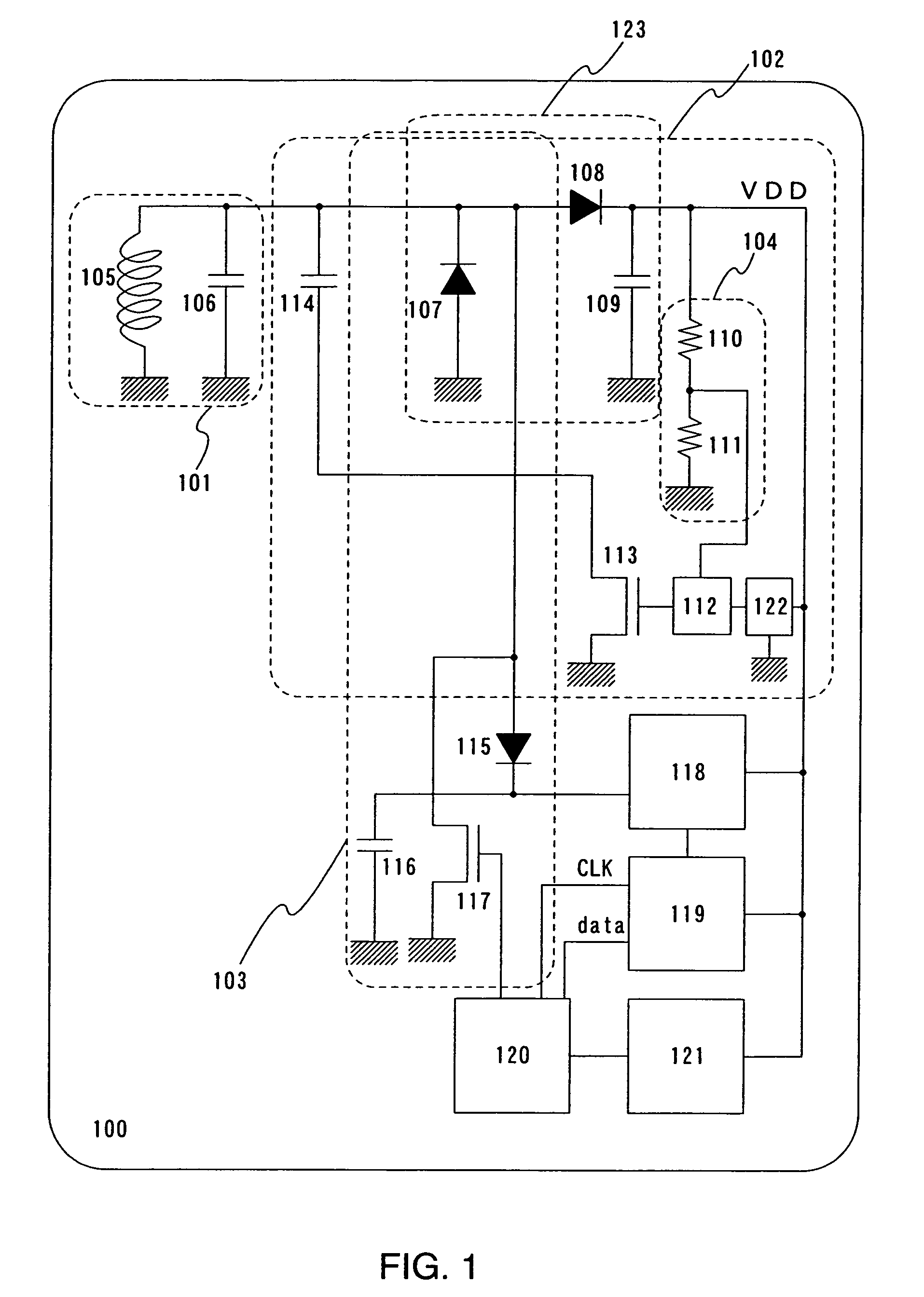
[0073]Referring to FIG. 22, description is made on a power supply circuit portion which has a different mode from the power supply circuit 102 shown in FIG. 1. FIG. 22 illustrates a circuit comprising a first antenna circuit 1801, a second antenna circuit 1802, a first converter circuit 1803, a second converter circuit 1804, a comparator circuit 1805, a switch element 1806 and a capacitor 1807. The second antenna circuit 1802 is configured so as to generate a lower voltage than the voltage generated in the first antenna circuit 1801. For example, the area occupied by an antenna in the second antenna circuit 1802 can be designed smaller than that in the first antenna circuit 1801. Alternatively, the antenna or a capacitor in the second antenna circuit 1802 may have different configurations from that of the first antenna circuit 1801 to obtain a slightly shifted resonance frequency. Though not shown, a monitor circuit as shown in FIG. 1 may be provided between the converter circuits a...
embodiment 2
[0077]Description is made now on the method for integrally forming TFTs which are used for the switch elements and diodes shown in embodiment mode over the same insulating substrate with reference to FIGS. 6A to 8. Note that N-channel TFTs and P-channel TFTs are taken as examples of semiconductor elements in this embodiment, however, semiconductor elements of the ID chip of the invention are not limited to them. In addition, the manufacturing method herein described is only an example, and the invention is not limited to such manufacturing method on an insulating substrate.
[0078]First, as shown in FIG. 6A, a base film 3001 formed of an insulating film such as a silicon oxide film, a silicon nitride film, a silicon oxynitride film is formed over a substrate 3000 formed of heat-resistant plastic or glass such as barium borosilicate glass and alumino borosilicate glass typified by Corning #7059 or #1737. For example, the base film 3001 has a lamination of a silicon oxynitride film 3001...
embodiment 3
[0104]In this embodiment, description is made on the manufacturing method which is from the formation of an ID chip up to the transfer thereof to a flexible substrate with reference to FIGS. 9A and 9B and FIGS. 10A and 10B. Note that N-channel TFTs and P-channel TFTs are used as the semiconductor elements in this embodiment, however, the semiconductor elements of the ID chip of the invention are not limited to them. In addition, the manufacturing method on an insulating substrate described herein is only an example, and the invention is not limited to this.
[0105]In accordance with the manufacturing steps described in Embodiment 2, steps up to the formation of the first and second interlayer insulating films are completed as shown in FIG. 8. However in this embodiment, a metal oxide film 4021 is formed between the substrate 3000 and the base film 3001. The metal oxide film 4021 may be an oxide of W, TiN, WN, Mo and the like, or an oxide of alloys of such elements. The metal oxide fil...
PUM
 Abstract
Description
Claims
Application Information
 - R&D
- Intellectual Property
- Life Sciences
- Materials
- Tech Scout
- Unparalleled Data Quality
- Higher Quality Content
- 60% Fewer Hallucinations
Browse by: Latest US Patents, China's latest patents, Technical Efficacy Thesaurus, Application Domain, Technology Topic, Popular Technical Reports.
© 2025 PatSnap. All rights reserved.Legal|Privacy policy|Modern Slavery Act Transparency Statement|Sitemap|About US| Contact US: help@patsnap.com


