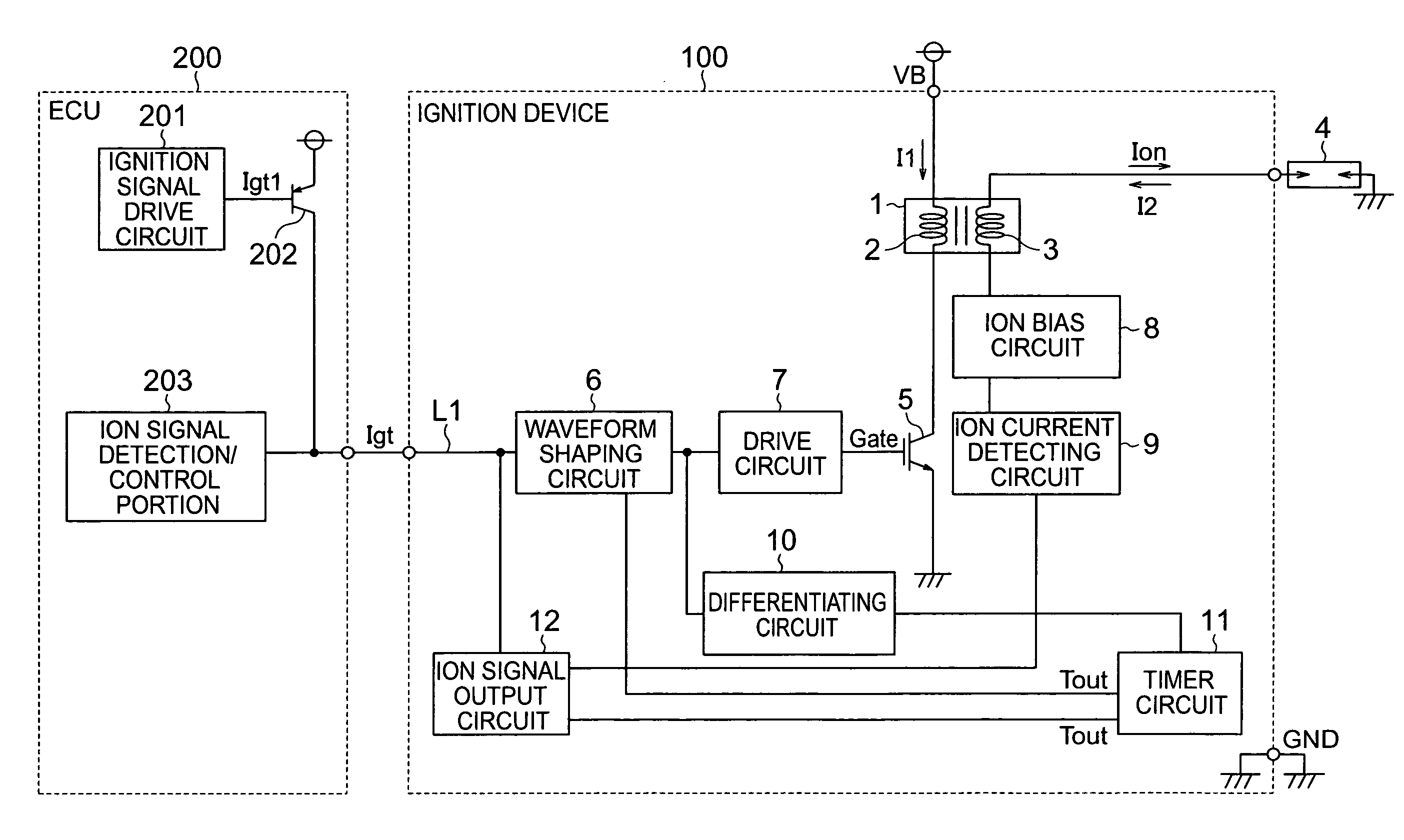
Ignition device of ignition control system for an internal combustion engine
a technology of ignition control system and ignition device, which is applied in the direction of electric control, machines/engines, instruments, etc., can solve the problems of increasing the number of parts of the ignition device, increasing the number of harnesses between the ignition device and the electronic control circuit, and increasing the number of parts of the devi
- Summary
- Abstract
- Description
- Claims
- Application Information
AI Technical Summary
Benefits of technology
Problems solved by technology
Method used
Image
Examples
first embodiment
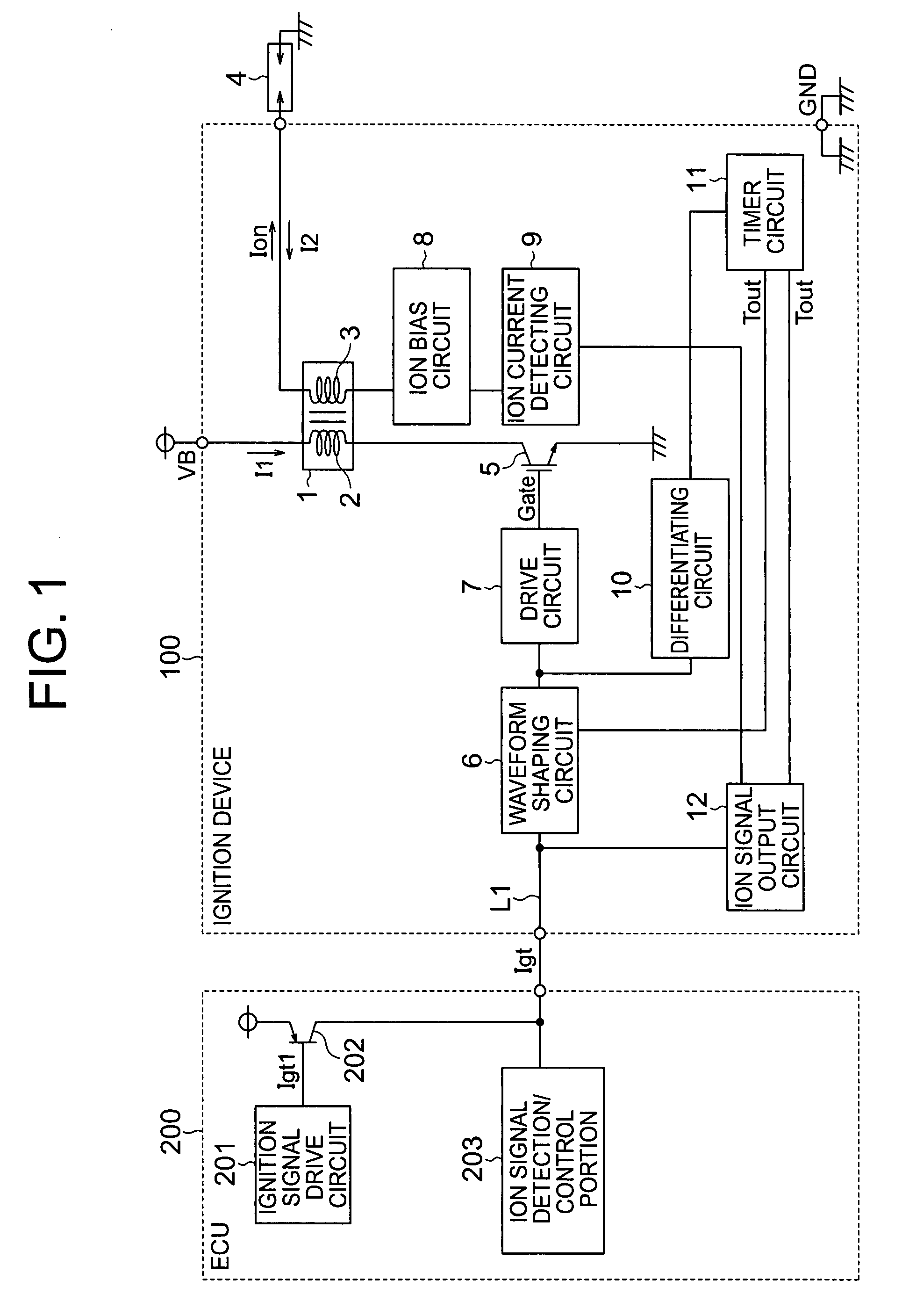
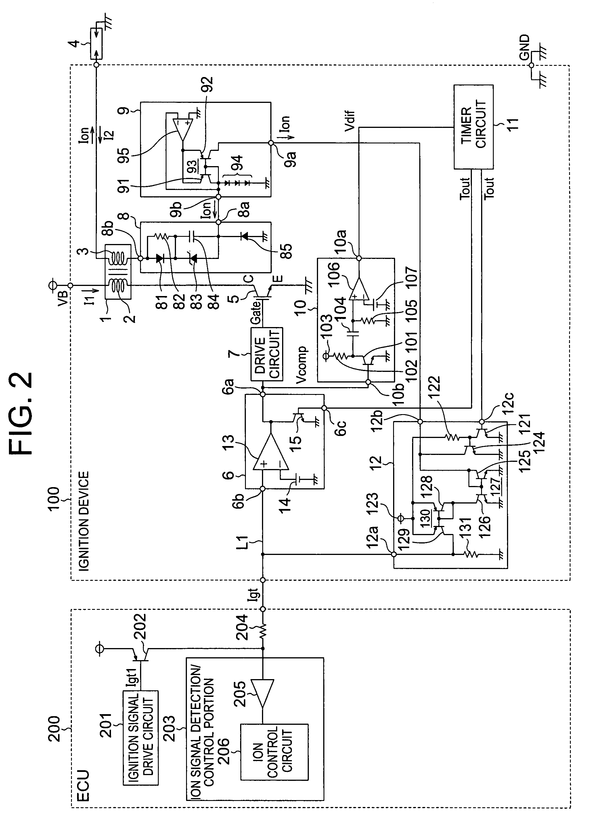
[0022]FIG. 1 is a diagram showing the configuration of an ignition control system for an internal combustion engine including an ignition device according to a first embodiment of the present invention. FIG. 1 shows a circuit for each one of cylinders. This circuit is composed of an ignition device 100 for igniting an ignition plug 4, and an electronic control unit (ECU) 200 including a computer (not shown in particular) for performing ignition control for the ignition device 100.
[0023]The ECU 200 is equipped with an ignition signal drive circuit 201 for supplying an ignition signal, a PNP transistor 202 for supplying a signal to a stage subsequent thereto based on the ignition signal output from the ignition signal drive circuit 201, and an ion signal detection / control portion 203 for detecting an ion signal as a failure diagnosis signal from the later-described ignition device 100 side and performing control based on a result of the detection of the ion signal.
[0024]The ignition d...
second embodiment
[0063]FIG. 5 is a diagram showing the configuration of an ignition control system for an internal combustion engine including an ignition device according to a second embodiment of the present invention. The ignition control system of FIG. 5 is obtained by eliminating the differentiating circuit 10, replacing the ion current detecting circuit 9 with a secondary current and ion current detecting circuit 90, and adding a secondary current pulse circuit 16 in the ignition control system shown in FIG. 1.
[0064]FIG. 6 is a diagram showing an example of the circuitry of respective components of the ignition control system for the internal combustion engine of FIG. 5. In this ignition control system, the secondary current and ion current detecting circuit 90 and the secondary current pulse circuit 16 are used. The second embodiment of the present invention is basically identical to the first embodiment of the present invention in other configurational details. In the second embodiment of th...
third embodiment
[0083]FIG. 8 is a diagram showing the configuration of an ignition control system for an internal combustion engine including an ignition device according to a third embodiment of the present invention. The ignition control system of FIG. 8 is obtained by replacing the timer circuit 11 with a timer circuit 110 in the ignition control system shown in FIG. 6. The third embodiment of the present invention is basically identical to the second embodiment of the present invention in other configurational details. In the third embodiment of the present invention, therefore, the same reference symbols are used to denote the components identical or equivalent to those of the second embodiment of the present invention respectively. The description of those components will be omitted.
[0084]The timer circuit 110 has three terminals, namely, output terminals 11aa and 11bb and an input terminal 11cc. The output terminal 11aa is connected to the input terminal 6c of the waveform shaping circuit 6 ...
PUM
 Abstract
Description
Claims
Application Information
 - R&D
- Intellectual Property
- Life Sciences
- Materials
- Tech Scout
- Unparalleled Data Quality
- Higher Quality Content
- 60% Fewer Hallucinations
Browse by: Latest US Patents, China's latest patents, Technical Efficacy Thesaurus, Application Domain, Technology Topic, Popular Technical Reports.
© 2025 PatSnap. All rights reserved.Legal|Privacy policy|Modern Slavery Act Transparency Statement|Sitemap|About US| Contact US: help@patsnap.com


