Optical module and optical communication device
a technology of optical communication device and optical module, which is applied in the direction of optical radiation measurement, instruments, semiconductor lasers, etc., can solve the problems of deteriorating waveform quality of optical signal at the time of high-speed modulation driving of light emitting elements, reducing the amount of light incident upon monitoring light receiving elements with an elevation of ambient temperature, etc., and achieves the effect of widening the operating temperature rang
- Summary
- Abstract
- Description
- Claims
- Application Information
AI Technical Summary
Benefits of technology
Problems solved by technology
Method used
Image
Examples
embodiment 1
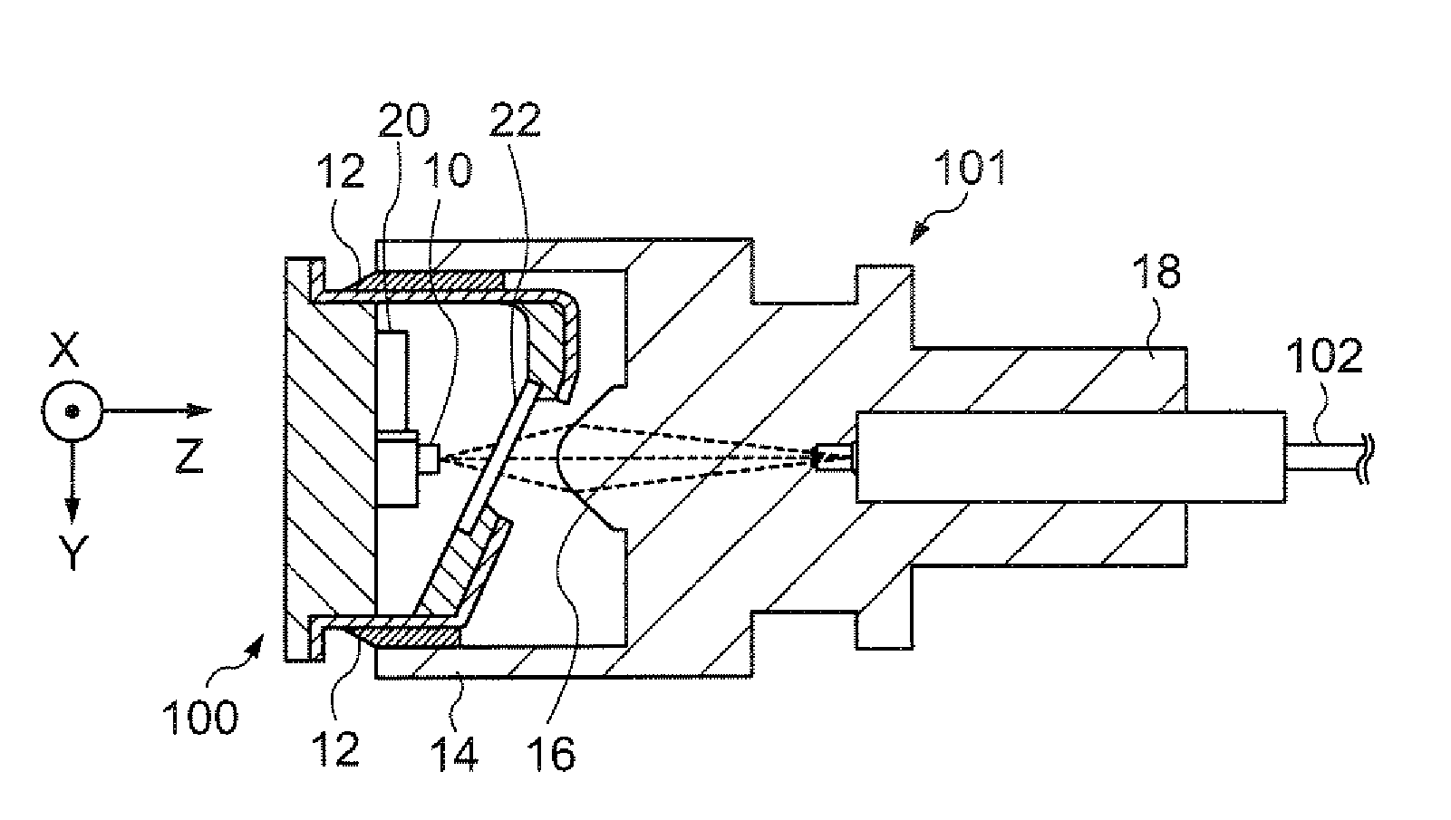
[0054]FIG. 1 is a cross-sectional view for describing the structure of an optical module in accordance with an embodiment of the invention. The optical module of the present embodiment is formed from a can package 100 and a connector part 101 positioned with each other, which are affixed with each other with an adhesive 12. The connector part 101 supports one end of an optical fiber 102, and optically couples the optical fiber 102 to a light emitting element 10 within the can package 100.
[0055] The can package 100 is formed from a housing made of metal or the like that packages the light emitting element 10. In the present embodiment, as the light emitting element 10, a VCSEL (vertical cavity surface emitting laser) diode that emits light in multimode is considered. The light emitting element 10 emits light with a wavelength of, for example, 850 nm. Also, the can package 100 is equipped with a monitoring light receiving element 20 as a system for monitoring light output of the ligh...
embodiment 2
[0068] An optical module in accordance with Embodiment 2 is similar to Embodiment 1 (FIG. 1). More specifically, the optical module of the present embodiment is formed from a can package 100 and a connector part 101 positioned with each other, which are affixed with each other by using an adhesive 12. The connector part 101 supports one end of an optical fiber 102, and optically couples the optical fiber 102 to a light emitting element 10 within the can package 100.
[0069] The can package 100 is formed from a housing made of metal or the like that packages the light emitting element 10. In the present embodiment, as the light emitting element 10, a VCSEL that emits light in multimode is considered. The light emitting element 10 emits light with a wavelength of, for example, 850 nm. Also, the can package 100 is equipped with a monitoring light receiving element 20 as a system for monitoring light output of the light emitting element 10 and a semitransparent glass plate (semitranspare...
embodiment 3
[0078] Next, an optical module in accordance with Embodiment 3 is described. The structure of the optical module in accordance with the present embodiment is generally the same as that of Embodiment 2 described above (see FIG. 1), and its illustration is therefore omitted. However, temperature characteristics of the monitoring light receiving element 20 and the semitransparent glass plate 22 are different from those of Embodiment 1, respectively. Their details are described below.
[0079]FIG. 12 is a graph showing one example of transmittance characteristic of the semitransparent glass plate in accordance with the present embodiment. In FIG. 12, temperatures (° C.) are indicated along the axis of abscissas, and transmittances T of the semitransparent glass plate 22 are indicated along the axis of ordinate. As shown in FIG. 12, the semitransparent glass plate 22 of the present embodiment has a characteristic in which its transmittance T increases (reflectivity decreases) with an incre...
PUM
 Abstract
Description
Claims
Application Information
 - R&D
- Intellectual Property
- Life Sciences
- Materials
- Tech Scout
- Unparalleled Data Quality
- Higher Quality Content
- 60% Fewer Hallucinations
Browse by: Latest US Patents, China's latest patents, Technical Efficacy Thesaurus, Application Domain, Technology Topic, Popular Technical Reports.
© 2025 PatSnap. All rights reserved.Legal|Privacy policy|Modern Slavery Act Transparency Statement|Sitemap|About US| Contact US: help@patsnap.com


