
Method and system for providing a modular server on USB flash storage

a server and modular technology, applied in the field of computer systems, can solve the problems of requiring a substantial investment of time on the part of users, ensuring that the computing device b>10/b> can function as a server, and ensuring that the user can provide the desired individual functions, etc., and achieve the effect of convenient use and low cos

Inactive Publication Date: 2008-12-16
KINGSTON DIGITAL CO LTD
View PDF9 Cites 12 Cited by
  • Summary
  • Abstract
  • Description
  • Claims
  • Application Information

AI Technical Summary

Benefits of technology

[0008]As Universal Serial Bus (USB) becomes a standard communication interface on the PC and digital imaging device, USB-based flash storage systems are starting to proliferate the consumer market. A traditional USB-based flash storage system tends to include a USB Local Control Program and one or more flash memory chips in addition to the USB connector. USB flash storage is becoming one of the most popular choices for external removable storage due to its simplicity, high performance and reliability.
[0009]If the PC or computing device has the capability in its BIOS to boot from a USB flash storage, it creates the possibility of incorporating server functionality into a USB flash storage. The server is thus modular and very portable. The actual storage drives on a server are no longer needed to reside on the same physical space with the server itself. It is possible to decouple the server from the storage drives completely. The server or storage drives can each evolve or upgrade independently of each other. Being able to easily hot swap the USB flash storage from the PC or computing device achieves improvements in service and support to the server itself.
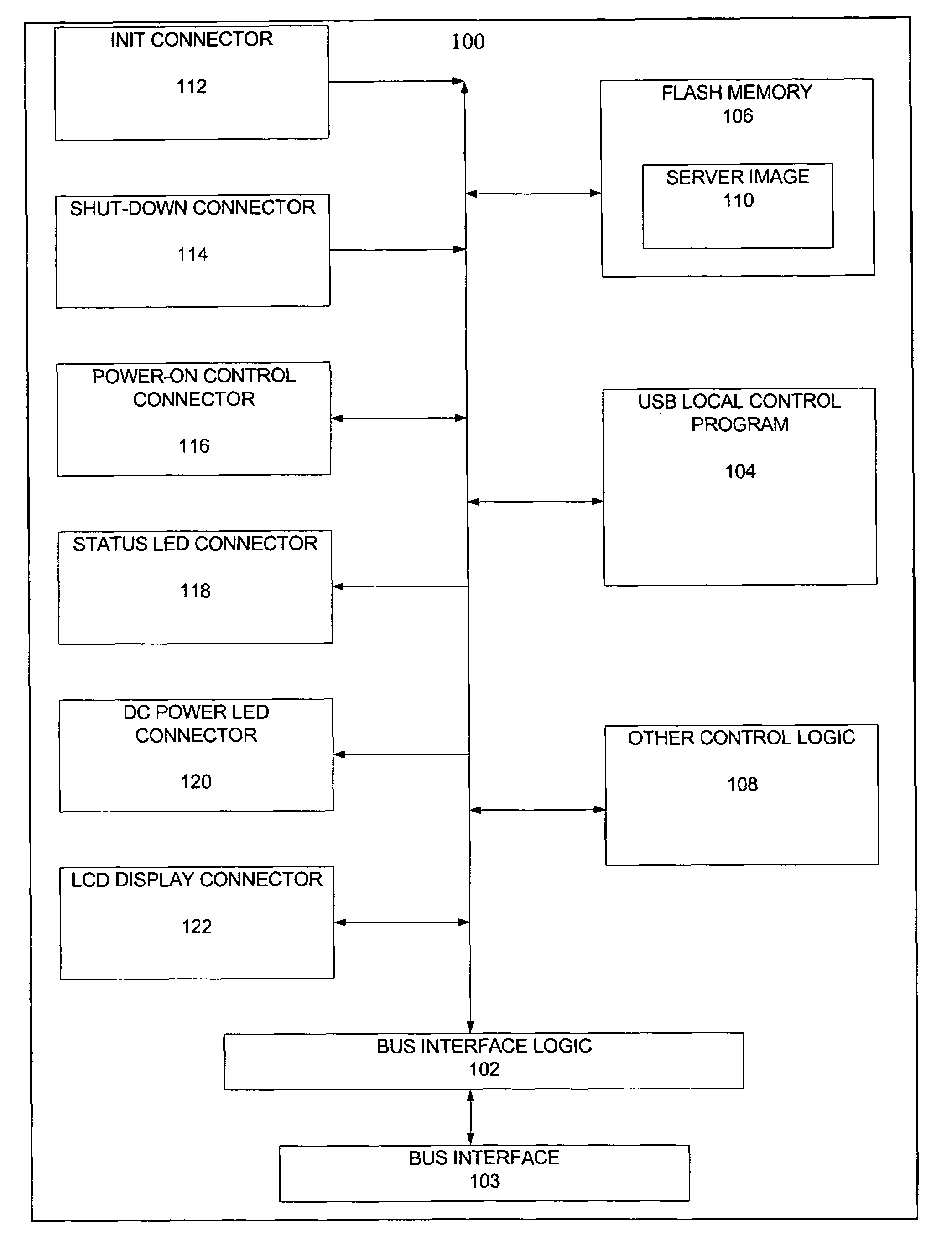
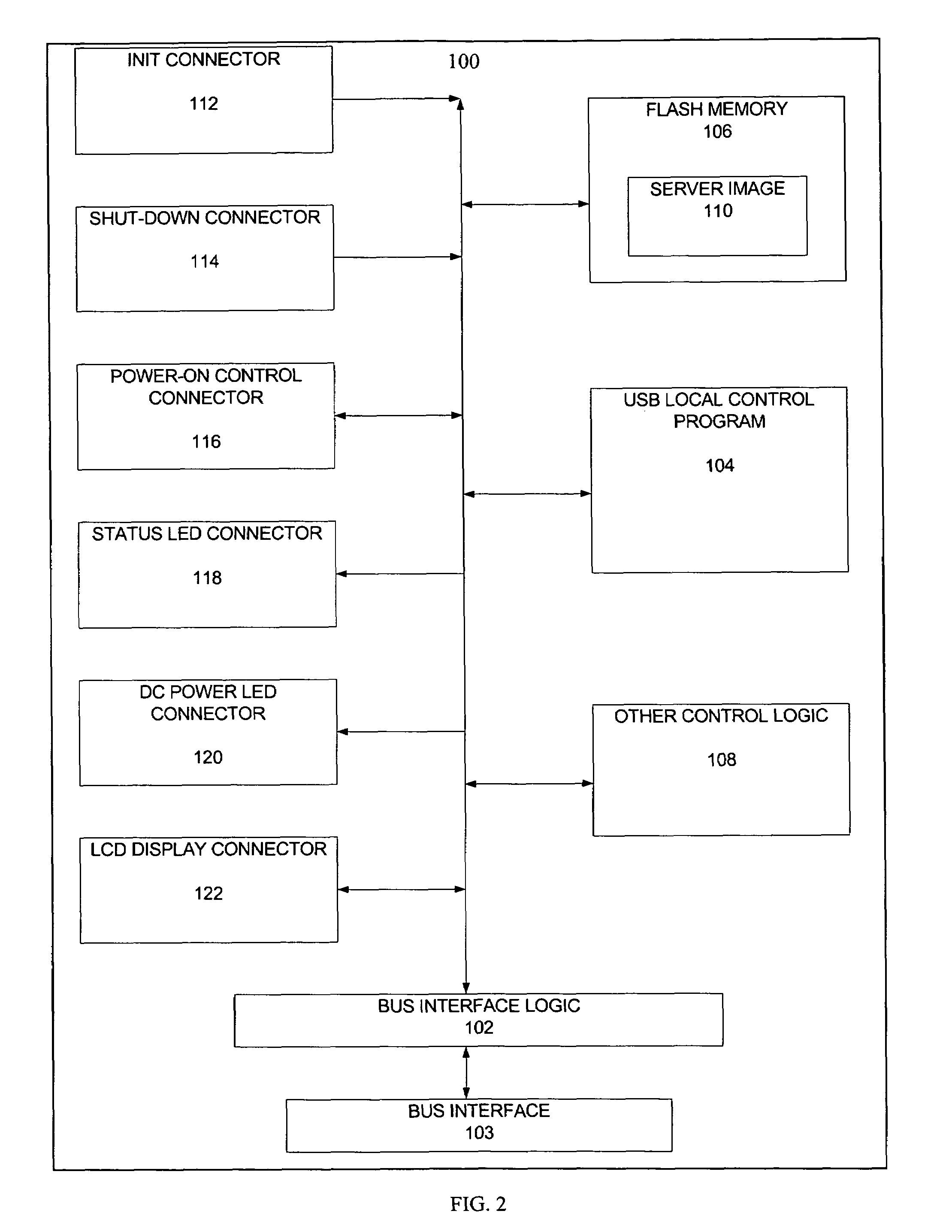
[0012]The present invention provides a method and system for providing a server on a computing device. The computing device includes at least a processor and an optional mass storage device. The method and system comprise providing bus interface logic, providing USB Local Control Program, a flash memory and, preferably, a set of control button connectors, light emitting diode (LED) connectors and a liquid crystal display (LCD) connector. The USB Local Control Program is coupled with the bus interface logic and the memory. The bus interface logic interacts with the computing device and allows the computing device to detect the system. The USB Local Control Program boots up the server and prepares the computing device for use as the server. The memory stores a server image for the server, which is provided to the computing device using the USB Local Control Program. The control button connectors allow the server to be turned on, shut down gracefully, or restored to its initial state, by a single press of buttons connected to these connectors. The LED and LCD connectors allow the system status to be displayed or shown. Different server images can be installed onto the same computing device, be it a workstation, a PDA or a notebook computer, by simply swapping in and out the USB flash storage while the computing device is still running or “hot”. Completely different server operating environments can be created as a matter of seconds instead of hours or days.
[0013]By virtue of the system and method disclosed herein, an inexpensive, easy to use mechanism is provided for allowing the computing device to be used as a server.

Problems solved by technology

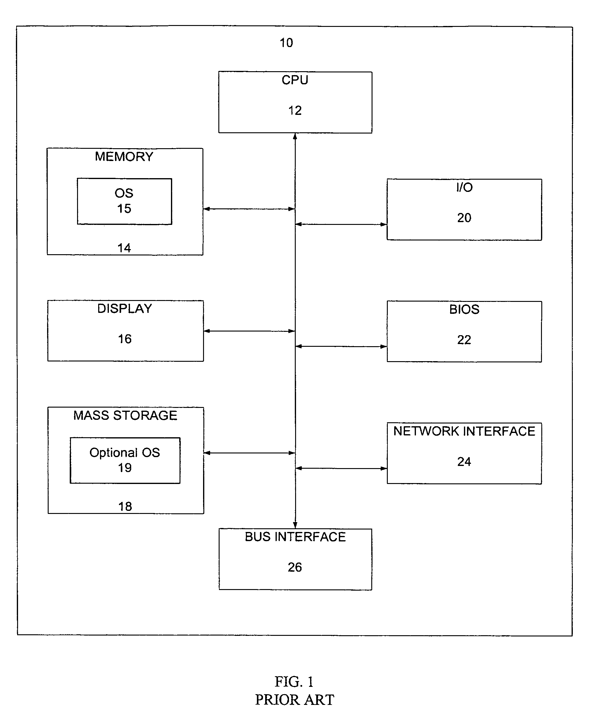
In either case, ensuring that the computing device 10 can function as a server is expensive.
Moreover, installing the software and tailoring the system to provide the desired individual functions requires a substantial investment of time on the part of the user.

Method used


Image

  • Method and system for providing a modular server on USB flash storage
  • Method and system for providing a modular server on USB flash storage
  • Method and system for providing a modular server on USB flash storage

Examples


Embodiment Construction

[0029]The present invention relates to an improvement in computer systems. The following description is presented to enable one of ordinary skill in the art to make and use the invention and is provided in the context of a patent application and its requirements. Various modifications to the preferred embodiment will be readily apparent to those skilled in the art and the generic principles herein may be applied to other embodiments. Thus, the present invention is not intended to be limited to the embodiment shown, but is to be accorded the widest scope consistent with the principles and features described herein.

[0030]The present invention provides a method and system for providing a modular server on a USB flash storage. The server-on-a-USB is installed on a computing device. The method and system include providing bus interface logic, providing a USB Local Control Program, flash memory and, preferably, a set of control button connectors, light emitting diodes (LED) connectors and...


PUM


Abstract

A method and system for providing a modular server-on-a-USB-flash-storage is disclosed. The server-on-a-USB-flash-storage is installed on a computing device. The method and system include providing USB interface logic, USB Local Control Program, a flash memory and a set of control button connectors, light emitting diodes (LED) connectors and a liquid crystal display (LCD) connector. The USB Local Control Program is coupled with the USB interface logic and the flash memory. The USB interface logic interacts with the computing device and allows the computing device to detect the server board. The USB Local Control Program boots up the server and prepares the computing device for use as the server. The flash memory stores a server image for the server, which is provided to the computing device using the USB Local Control Program. The control button connectors allow the server to be turned on, shut down gracefully, or restored to its initial state, by a single press of buttons connected to these connectors. The LED and LCD connectors allow the system status to be displayed or shown. Different server images can be installed onto the same computing device, be it a workstation, a PDA or a notebook computer, by simply swapping in and out the USB flash storage while the computing device is still running or “hot.”

Description

CROSS REFERENCES TO RELATED PATENT APPLICATIONS[0001]This application is a continuation-in-part of Ser. No. 10 / 002,652, now issued U.S. Pat. No. 7,103,765 filed Oct. 19, 2001.BACKGROUND OF THE INVENTION[0002]1. Field of the Invention[0003]The present invention relates to computer systems, and more particularly to a method and system for providing a server on a generalized computing device.[0004]2. Background Art[0005]FIG. 1 depicts a generalized computing device 10. The computing device 10 includes at least a CPU 12 and an optional mass storage 18, such as a hard disk. The computing device 10 may also include other features. The computing device depicted in FIG. 1 also includes a memory 14 such as a flash memory, an operating system (OS) 15, a display 16, an input / output device 20 such as a keyboard, BIOS 22, a network interface 24 and a bus interface 26. An optional operating system (OS) 19 may reside on the mass storage 18. Communication to a network (not shown) is carried out thr...

Claims


Application Information

Patent Timeline
Patent Type & Authority Patents(United States)
IPC IPC(8): G06F15/177G06F9/445
CPCG06F9/4401G06F9/44573
Inventor CHEN, BEN WEI
Owner KINGSTON DIGITAL CO LTD
Learn More