
Replaceable brush seal elements

a technology of replacement brush seals and elements, which is applied in the direction of engine seals, gas turbine plants, machines/engines, etc., can solve the problems of adding to the complexity and cost of the brush seals purchased by the operators of these turbines, and achieves the effect of convenient use and low cos

Active Publication Date: 2012-05-22
RAYTHEON TECH CORP
View PDF22 Cites 11 Cited by
  • Summary
  • Abstract
  • Description
  • Claims
  • Application Information

AI Technical Summary

Benefits of technology

[0004]Accordingly, it is an object of the present invention to provide a brush seal assembly which is inexpensive and easily can be used to replace existing brush seals.
[0005]It is a further object of the present invention to provide a method of repairing a brush seal which is easy and inexpensive to perform.

Problems solved by technology

The use of this type of configuration adds to the complexity and cost of the brush seals purchased by operators of these turbines.

Method used


Image

  • Replaceable brush seal elements
  • Replaceable brush seal elements
  • Replaceable brush seal elements

Examples


first embodiment

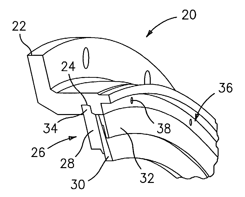
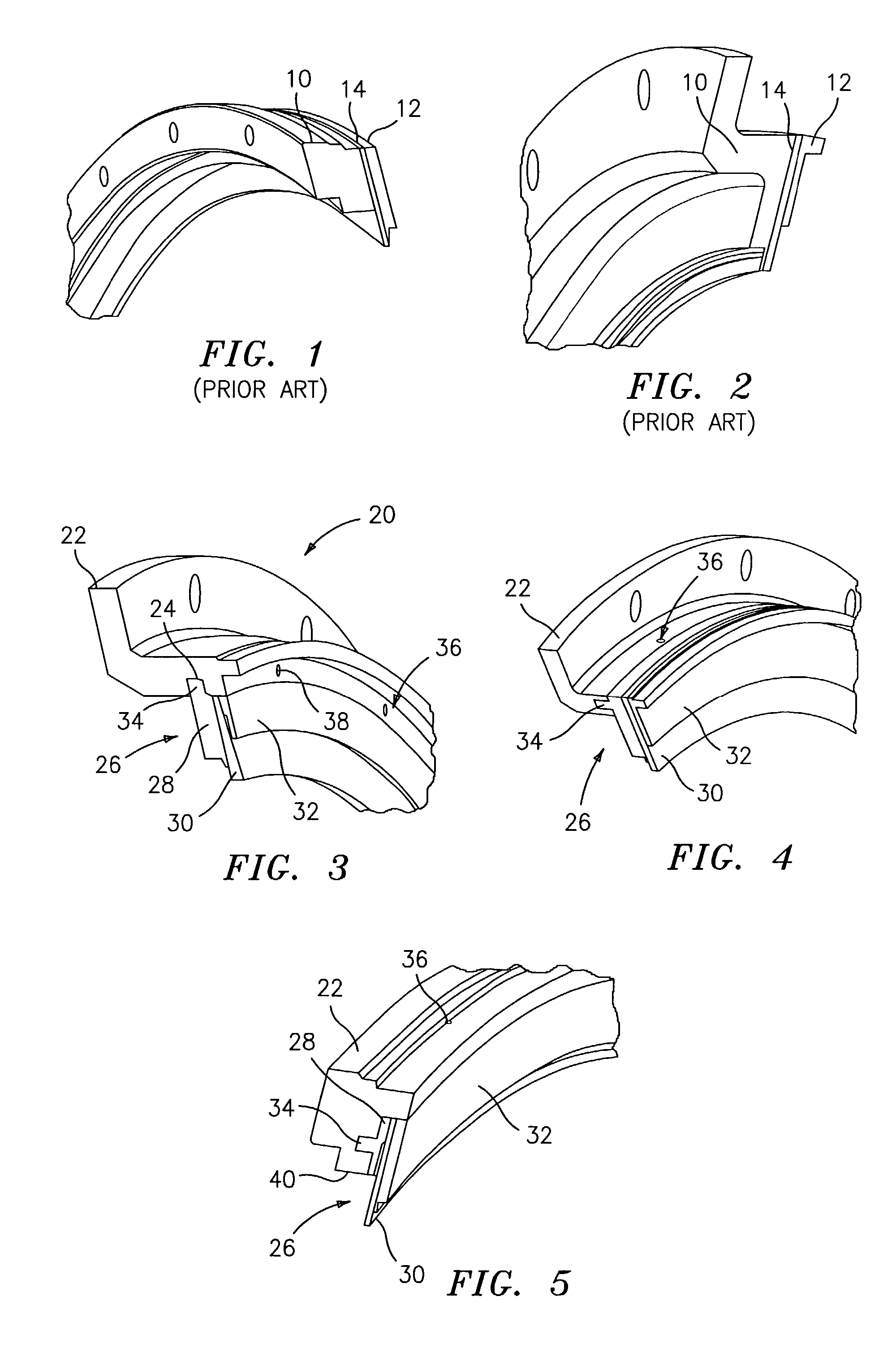
[0019]Referring now to the drawings, FIG. 3 illustrates a brush seal assembly 20 in accordance with the present invention. In this assembly, an L-shaped flange 22 having an annular groove 24 machined therein is utilized. The flange 22 may be a new element or may be a refurbished flange element which previously had a portion of an integral back plate removed. The assembly further comprises a replacement brush seal element 26 having means for preventing rotation of the brush seal element 26 relative to the flange 22. The replacement brush seal element 26 comprises an integral back plate 28, brushpack 30, and side plate 32. The back plate 28, the brushpack 30 and the side plate 32 may be joined together either by welding or any other suitable technique. The rotation prevention means comprises a tongue 34 which is integrally formed with the back plate 28 and which fits or slides into the groove 24. The tongue 34 is provided with a series of openings which align with openings 36 formed i...

second embodiment

[0022]Referring now to FIG. 4, a brush seal element 26 is illustrated. In this embodiment, an axially extending groove 24 has been machined into the flange 22. Further, the tongue 34 is axially aligned with the groove 24. As can be seen from this Figure, the pins 38 are now oriented in a radial direction.

[0023]FIG. 5 illustrates yet another embodiment of a brush seal element 26 in accordance with the present invention. The brush seal element26 is identical to that of FIG. 4 except for the back plate 28 being shorter than the back plate used in the embodiment of FIG. 4. In this embodiment, the back plate 28 does not extend below the surface 40 of the flange 22.

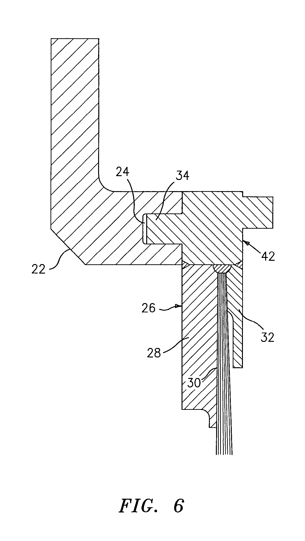
[0024]FIG. 6 illustrates yet another embodiment of a brush seal element in accordance with the present invention. In this embodiment, the flange 22 has an axially extending groove 24 and the brush seal element 26 includes a back plate 28, a brushpack 30 and a side plate 32. The brush seal element further includes a locating rin...


PUM


Abstract

The present invention relates to replaceable brush seal assemblies for use with turbines such as industrial gas turbines. In accordance with the present invention, a brush seal assembly comprises a flange, a brush seal mounted to the flange, and retainers preventing rotation of the brush seal relative to the flange. A method of repairing a brush seal having a back plate, side plate, and bristles is also disclosed. The method comprises the steps of removing the side plate and the bristles from the back plate, and securing a second brush seal to the back plate.

Description

BACKGROUND OF THE INVENTION[0001]The present invention relates to replaceable brush seal elements for turbines, particularly industrial gas turbines.[0002]A wide variety of brush seals are known in the art. Such brush seals are exemplified by U.S. Pat. Nos. 5,066,024 to Reisinger et al.; 6,168,162 to Reluzco et al.; 5,704,760 to Bouchard et al.; 5,630,590 to Bouchard et al.; and 6,318,728 to Addis et al.[0003]Current industrial gas turbines utilize brush seal configurations with substantial cross sections. Such brush seal configurations are shown in FIGS. 1 and 2. These configurations include an integral back plate and flange structure 10, a side plate 12, and a brush pack 14 positioned between the structure 10 and the side plate 12. The brush pack typically comprises a series of bristles and typically runs 0.035 to 0.100 inches (0.0889 to 0.254 cm.) in axial width. The use of this type of configuration adds to the complexity and cost of the brush seals purchased by operators of the...

Claims


Application Information

Patent Timeline
Patent Type & Authority Patents(United States)
IPC IPC(8): F16J15/447F16J15/44F01D11/00F02B39/00F02C7/28F16J15/22F16J15/32
CPCF16J15/3288
Inventor ADDIS, MARK E.
Owner RAYTHEON TECH CORP
Learn More