
Method for controlling an internal combustion engine

Inactive Publication Date: 2008-12-09
MAHLE INT GMBH
View PDF10 Cites 0 Cited by
  • Summary
  • Abstract
  • Description
  • Claims
  • Application Information

AI Technical Summary

Benefits of technology

[0005]The present invention relates to the problem of showing a method for an internal combustion engine that will permit reduced fuel consumption and can be implemented comparatively inexpensively.
[0007]The invention is based on the general idea of implementing the fresh gas flow rate control in a dethrottled internal combustion engine with the help of clocked valves arranged in the individual fresh gas pipes, whereby at the same time the fuel injection is coordinated with the switching times of the clocked valves. The quantity of fresh gas or the fresh gas charge required for the respective load state of internal combustion engine can be adjusted in a controlled manner on each cylinder through a suitable choice of the closing points in time and the opening points in time of the individual clocked valves. A throttle mechanism for load-dependent throttling of the fresh gas supply is thus dispensable. To this extent, the present invention makes use of the advantages of a dethrottled internal combustion engine. In conjunction with the clocked valves which can be produced relatively inexpensively, an inexpensive approach is thus obtained. Furthermore, the coordination of the injection processes with the clock points of the clocked valves also leads to an additional improvement in the combustion process. Thus, on the whole, a definite improvement in the combustion process can be achieved with regard to emissions and fuel consumption in a comparatively inexpensive manner.
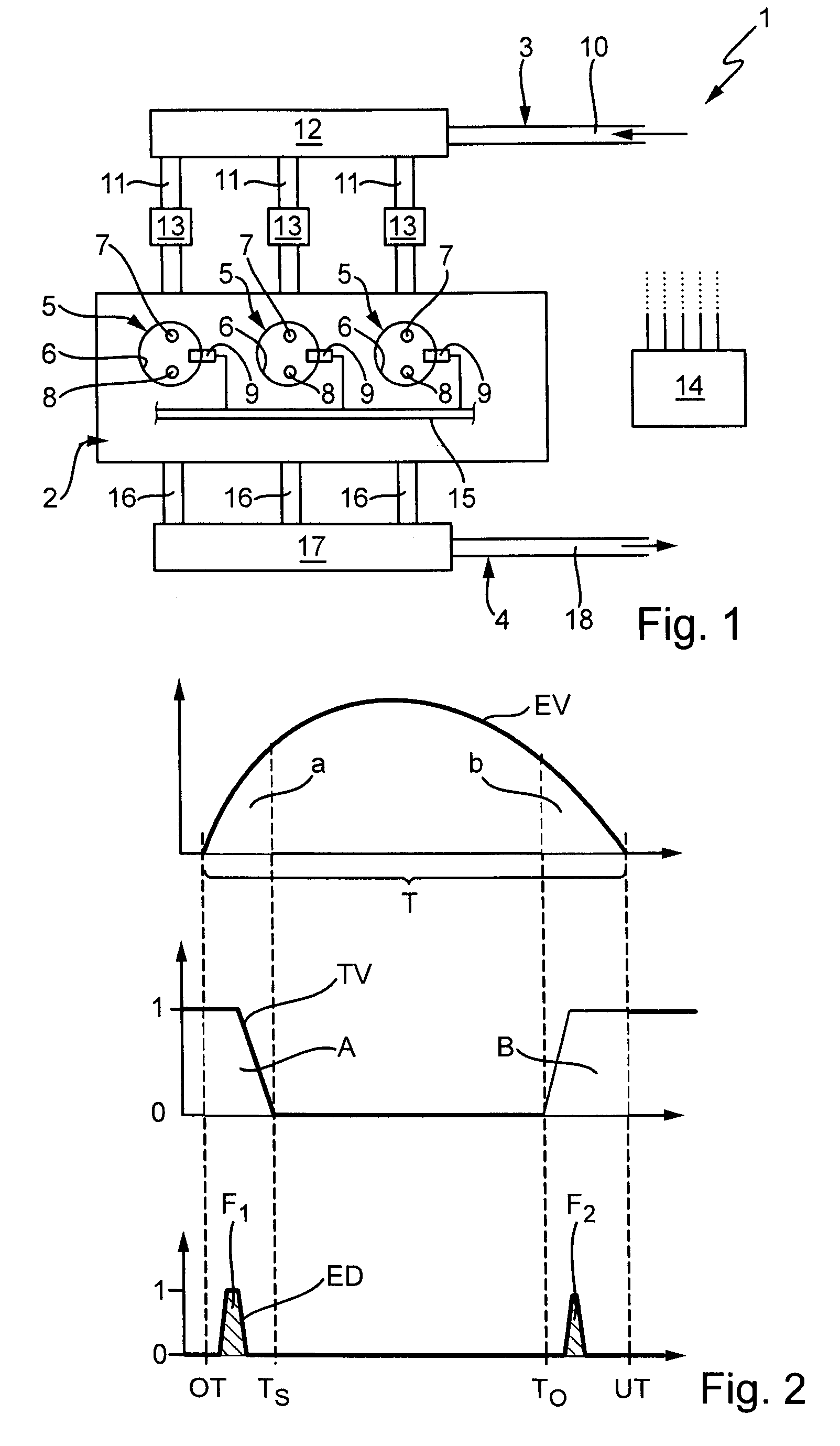
[0008]In an advantageous embodiment, the clocked valves can be controlled at least during partial-load operation of the internal combustion engine so that there are at least two fresh gas charging phase at a distance from one another in time in the respective cylinder during an intake cycle. During the first charging phase, there is a more or less basic charging of the respective cylinder which can be utilized to advantage to produce the mixture, for example. With the second charging phase, the desired flow state, e.g., spiral flow and / or tumble flow, can be produced in the combustion chamber at a point in time that is comparatively close to the ignition point in time, which is also advantageous from the standpoint of pollution emissions and the efficiency of the combustion process.
[0009]In the case of a controller operating with two or more fresh gas charging phases, it may be advantageous, at least for certain operating states of the internal combustion engine, for a separate fuel injection to be performed during each of two separate fresh gas charging phases. For example, the second fuel injection allows the mixture produced with the help of the first injection to be made richer to thereby significantly increase the ignitability of the overall charging.

Problems solved by technology

Such electromagnetic valve controls are much more expensive, however, than traditional valve drives controlled by camshafts.

Method used


Image

  • Method for controlling an internal combustion engine
  • Method for controlling an internal combustion engine

Examples


Embodiment Construction

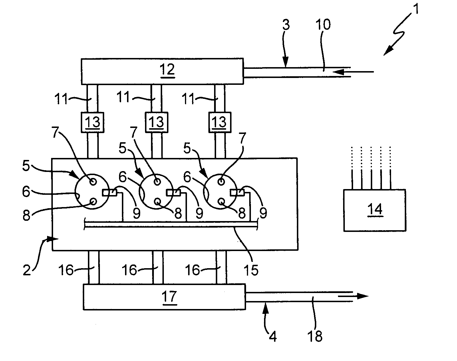
[0016]According to FIG. 1, an internal combustion engine 1 comprises an engine block 2, a fresh gas system 3, which supplies fresh gas to the engine block 2, and an exhaust system 4, which removes exhaust gas from the engine block 2. The internal combustion engine 1 is preferably arranged in a motor vehicle.

[0017]The engine block 2 contains multiple cylinders 5; three cylinders 5 are shown in this example without restricting the general scope in any way. Each cylinder 5 encloses a combustion chamber 6 and guides a piston (not shown) in a known manner. At least one intake valve 7 and at least one exhaust valve 8 are allocated to each cylinder 5. The intake valves 7 are designed and arranged in such a way that they are able to open and close a fresh gas intake, not discussed further here, of the respective combustion chamber 6 in the usual manner. In a corresponding manner, the exhaust valves 8 are designed and arranged in such a way that they are able to open and close an exhaust out...


PUM


Abstract

A method for controlling a dethrottled internal combustion engine, which has a shared fresh gas line which supplies fresh gas to fresh gas pipes, which in turn supply fresh gas to each cylinder. The engine has at least one intake valve per cylinder, a clocked valve per fresh gas pipe for opening and closing the gas pipe and a fuel injector for each cylinder, for metered addition of fuel. The chronological location of the injection time of the fuel is adjusted for the respective cylinder as a function of a point in time of a change in the switch position of the respective clocked valve, to improve the emission values of the engine. In addition, the clocked valves are controlled so that the metered addition of fresh gas is accomplished for the respective cylinder.

Description

CROSS REFERENCE TO RELATED APPLICATIONS[0001]Applicants claim priority under 35 U.S.C. §119 of German Application No. 10 2006 023 853.2 filed May 19, 2006.BACKGROUND OF THE INVENTION[0002]The present invention relates to a method for controlling a dethrottled internal combustion engine. The invention also relates to a device for controlling a dethrottled internal combustion engine. In addition, the invention relates to a dethrottled internal combustion engine equipped with such a control device.[0003]DE 103 44 759 A1 discloses a method for controlling an internal combustion engine. The internal combustion engine controlled by the known method comprises a joint fresh gas line that supplies fresh gas to a plurality of fresh gas pipes which in turn each carry fresh gas to a cylinder. The internal combustion engine also comprises at least one intake valve per cylinder and also one pulse charging valve per fresh gas pipe for opening and closing the respective fresh gas pipe. Furthermore,...

Claims


Application Information

Patent Timeline
IPC IPC(8): F02D41/00F02D41/04
CPCF02B29/083F02D37/00F02D41/0002F02D41/401F02D41/402Y02T10/146Y02T10/44Y02T10/42Y02T10/18Y02T10/12Y02T10/40
Inventor ELSASSER, ALFREDRUCKAUF, JORG
Owner MAHLE INT GMBH
Learn More