
Startup burner assembly for snow melting apparatus and method of snow melting

a technology of snow melting apparatus and starter assembly, which is applied in the direction of combustion process, combustion ignition, discharged material handling, etc., can solve the problems of restricting the use of such equipment and water supply in sufficient quantities, and achieve the effect of improving the efficiency of the debris removal process

Active Publication Date: 2008-11-25
TRECAN COMBUSTION
View PDF20 Cites 5 Cited by
  • Summary
  • Abstract
  • Description
  • Claims
  • Application Information

AI Technical Summary

Benefits of technology

"The present invention provides a startup burner assembly for a snow melting apparatus that allows for ignition without initially supplying water to cool the system. The assembly includes a fuel burner with adjustable combustion output, a combustion chamber with discharge holes to allow for the egression of products of combustion, and an air cooling assembly to supply air to cool the system. The assembly also includes a housing to enclose the combustion chamber and a crossover duct to connect the housing of the load burner assembly for cooling purposes. The technical effect of the invention is to provide a more efficient and effective snow melting apparatus with improved ignition capabilities and reduced risk of damage to the system."

Problems solved by technology

The instantaneous mixing and transfer of heat to the water causes an immediate decrease in bulk density of the mixture causing the mixture to rise vertically up the annular space inside the weir and violent discharge thereof out of the opening at the top of the weir.
A common problem of such prior art devices is that water must be supplied in sufficient quantity to provide cooling of the burner assembly prior to ignition of the burner.
This results in a need for water to be readily available at the site of operation, restricting the use of such equipment to sites having a water source in close proximity.

Method used


Image

  • Startup burner assembly for snow melting apparatus and method of snow melting
  • Startup burner assembly for snow melting apparatus and method of snow melting
  • Startup burner assembly for snow melting apparatus and method of snow melting

Examples


Embodiment Construction

[0050]Snow melters used in snow removal typically incorporate at least one fuel burner to generate the heat required for melting collected snow. In such devices, overheating of the burner is prevented through the use of water as a coolant. This cooling may be provided by pumping water through a jacket surrounding the burner assembly and / or by immersion of at least a portion of the burner assembly into a reservoir of water. The present invention overcomes this requirement for initial water cooling by providing a startup burner assembly which enables burner ignition without initially supplying water as a coolant.

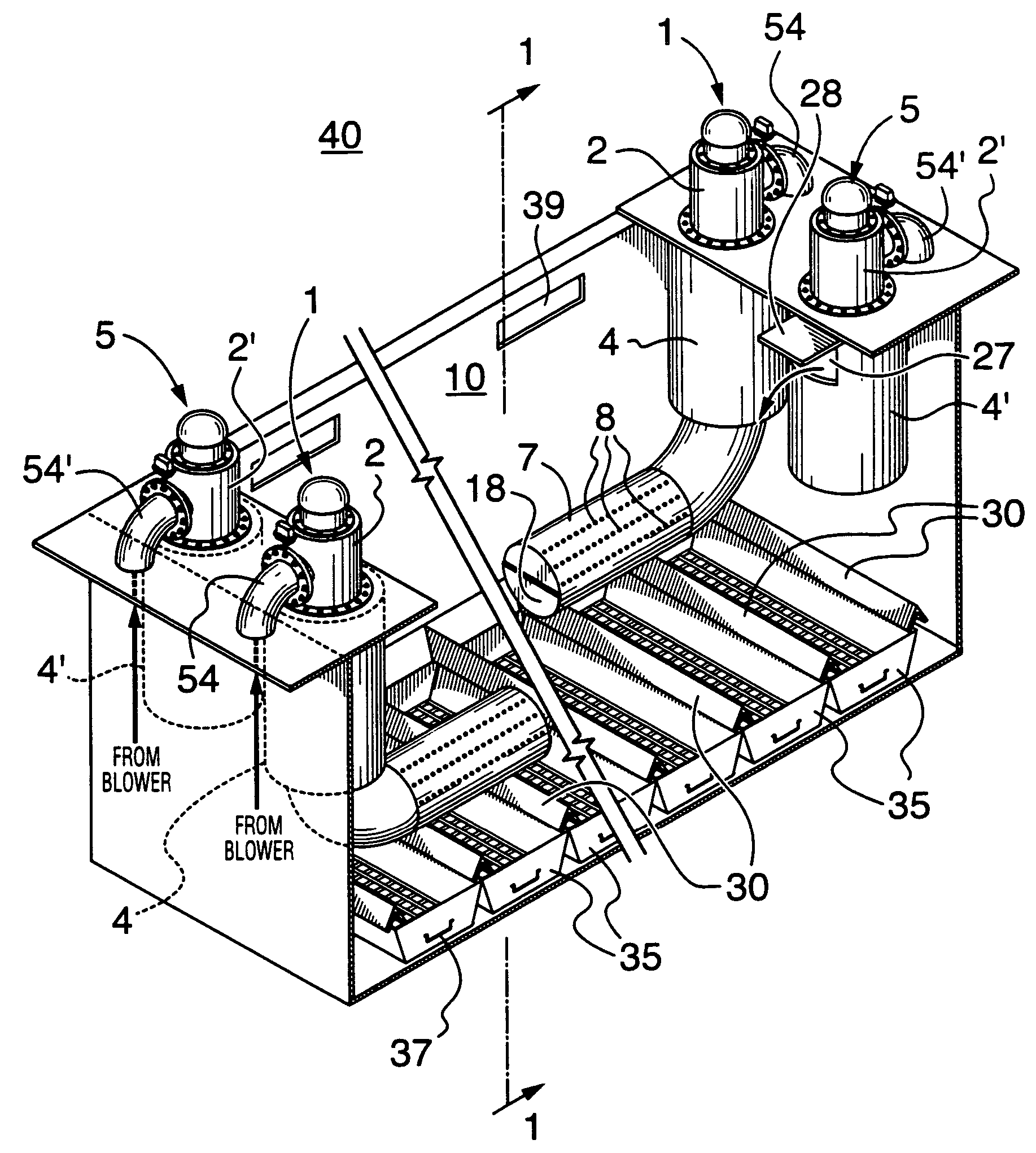
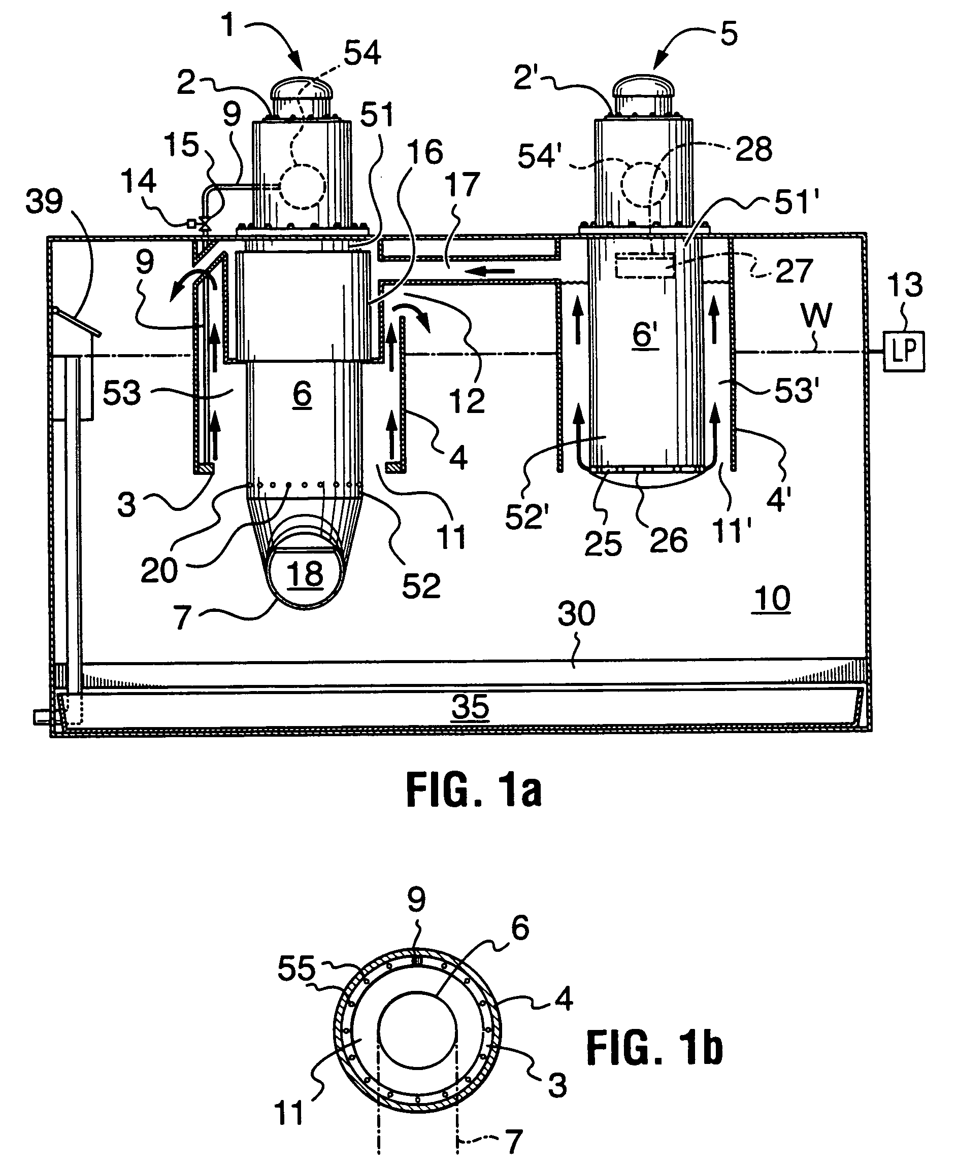
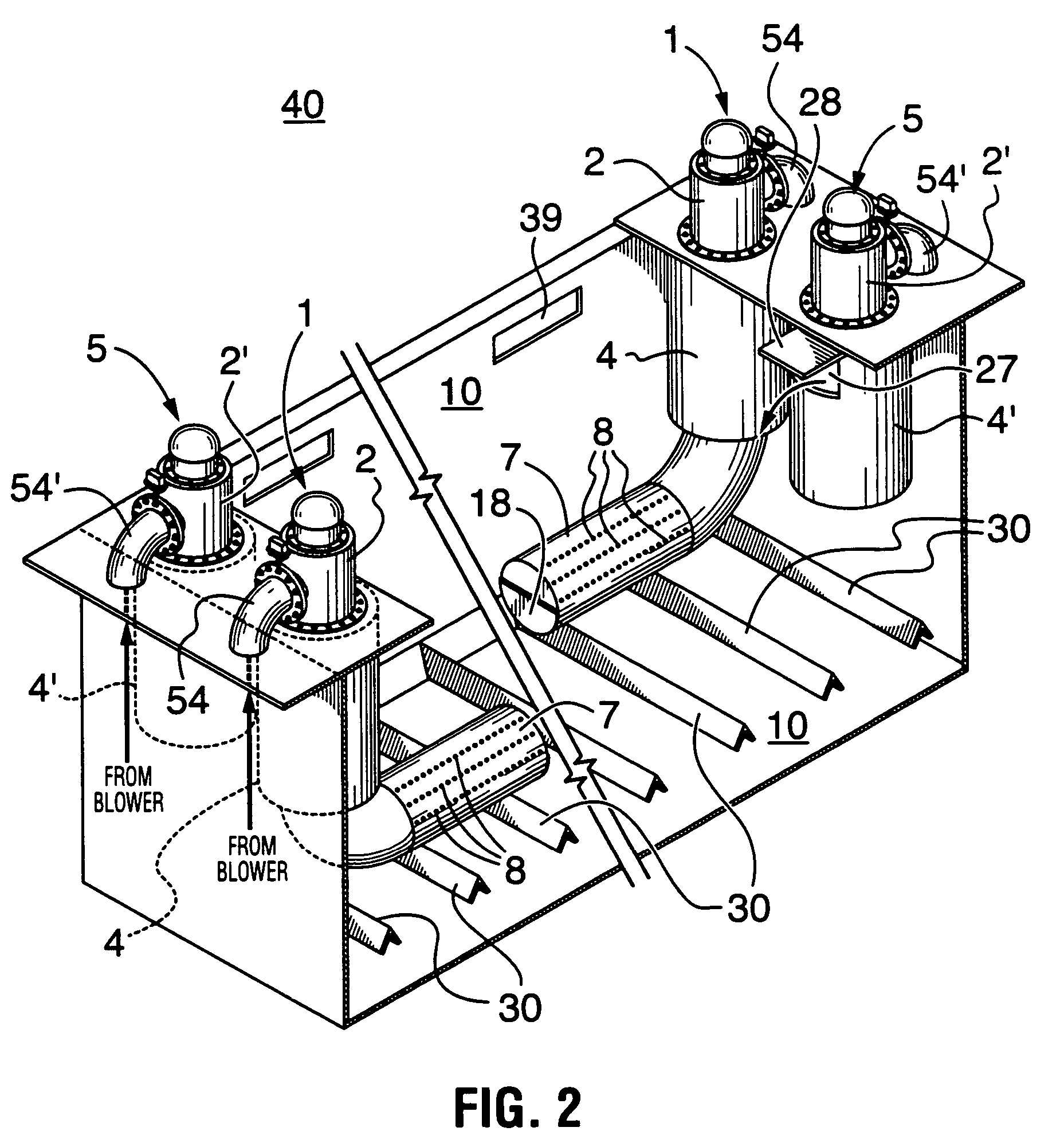
[0051]Most snow melters commonly known and used in the art may be fitted with the burner assembly of the present invention. These include single or multi-burner devices. For illustration FIG. 1a shows a double-burner snow melting device which incorporates an example of the startup burner assembly (1) of the present invention, mounted operably to a receptacle, or tank (10).

[005...


PUM


Abstract

A startup burner assembly for use in snow melting applications, and which permits initiation of snow melting without first supplying water as a coolant. The startup burner assembly comprises a fuel burner having adjustable combustion output and a nozzle to facilitate the emergence of products of combustion, and a combustion chamber having a first portion in substantially air-tight communication with the fuel burner and enclosing the nozzle and a second portion shaped and dimensioned for disposition into a snow melting receptacle or pit. The combustion chamber has a plurality of discharge holes formed at least on the second portion thereof to permit the egress of products of combustion from the fuel burner into the tank or pit, and thereby permit agitation and melting of snow loaded therein, The startup burner assembly also includes an air cooling assembly for supplying air to cool at least the first portion of the combustion chamber.

Description

FIELD OF THE INVENTION[0001]The present invention relates to snow melting equipment, and more specifically, to improvements in traditional snow melters which utilize heat to melt and thus dispose of large amounts of snow. In particular, the invention relates to a startup snow melting apparatus which permits burner ignition without initially supplying water as a coolant.BACKGROUND OF THE INVENTION[0002]Snow melting devices known in the art commonly utilize a burner unit or assembly to provide heat to a snow melting medium, typically water. The heated medium is then used in various ways to melt the snow.[0003]Canadian Patent No. 780,673 and U.S. Pat. No. 3,187,743 (both to Primas) disclose a snow melting device commonly known in the art. This device includes a tank and a fuel burner assembly. The burner assembly includes a downwardly extending downcomer tube which encloses the fuel burner nozzle. The downcomer tube is provided with an opening at the bottom for the outflow of combustio...

Claims


Application Information

Patent Timeline
Patent Type & Authority Patents(United States)
IPC IPC(8): E01H5/10F24C15/16F23C3/00F23D14/10F23D23/00F23D99/00
CPCE01H5/102F23C3/004F23D14/105F23D23/00F23D99/006F23D2214/00F23D91/04
Inventor BURNETT, DAVIDMEREDITH, STEVENBURNETT, GLEN
Owner TRECAN COMBUSTION
Learn More