
Electro-thermal nanoparticle generator

a nanoparticle generator and electro-thermal technology, applied in the direction of machines/engines, marine propulsion, vessel construction, etc., can solve the problems of chemical reaction chamber and acceleration system inside the diffuser separation, no system has been designed that would allow for the variability of particle size and mass

Inactive Publication Date: 2008-11-25
BOSSMANN STEFAN H +1
View PDF39 Cites 13 Cited by
  • Summary
  • Abstract
  • Description
  • Claims
  • Application Information

AI Technical Summary

Benefits of technology

"The current invention is about a device and method for creating small particles that can be used for flight propulsion, plasma generation, and controlled particle emission for deposition. The device can also insert heavy metals into the particle stream. The technical effects of this invention include the ability to generate variable thrust and specific impulse for flight propulsion systems, as well as a controlled particle emission for nanoparticle deposition."

Problems solved by technology

A disadvantage of the disclosed plasma accelerator is the use of a propellant with a relatively small molecular mass.
Ions become magnetically accelerated with a specific impulse between 800 and 2500 s. A disadvantage of this propulsion system is the separation of chemical reaction chamber and acceleration system inside the diffuser.
Despite the significant level of interest in ionized particle generators, no system has been designed that would allow for the variability of particle size and mass.

Method used


Image

  • Electro-thermal nanoparticle generator
  • Electro-thermal nanoparticle generator
  • Electro-thermal nanoparticle generator

Examples


second embodiment

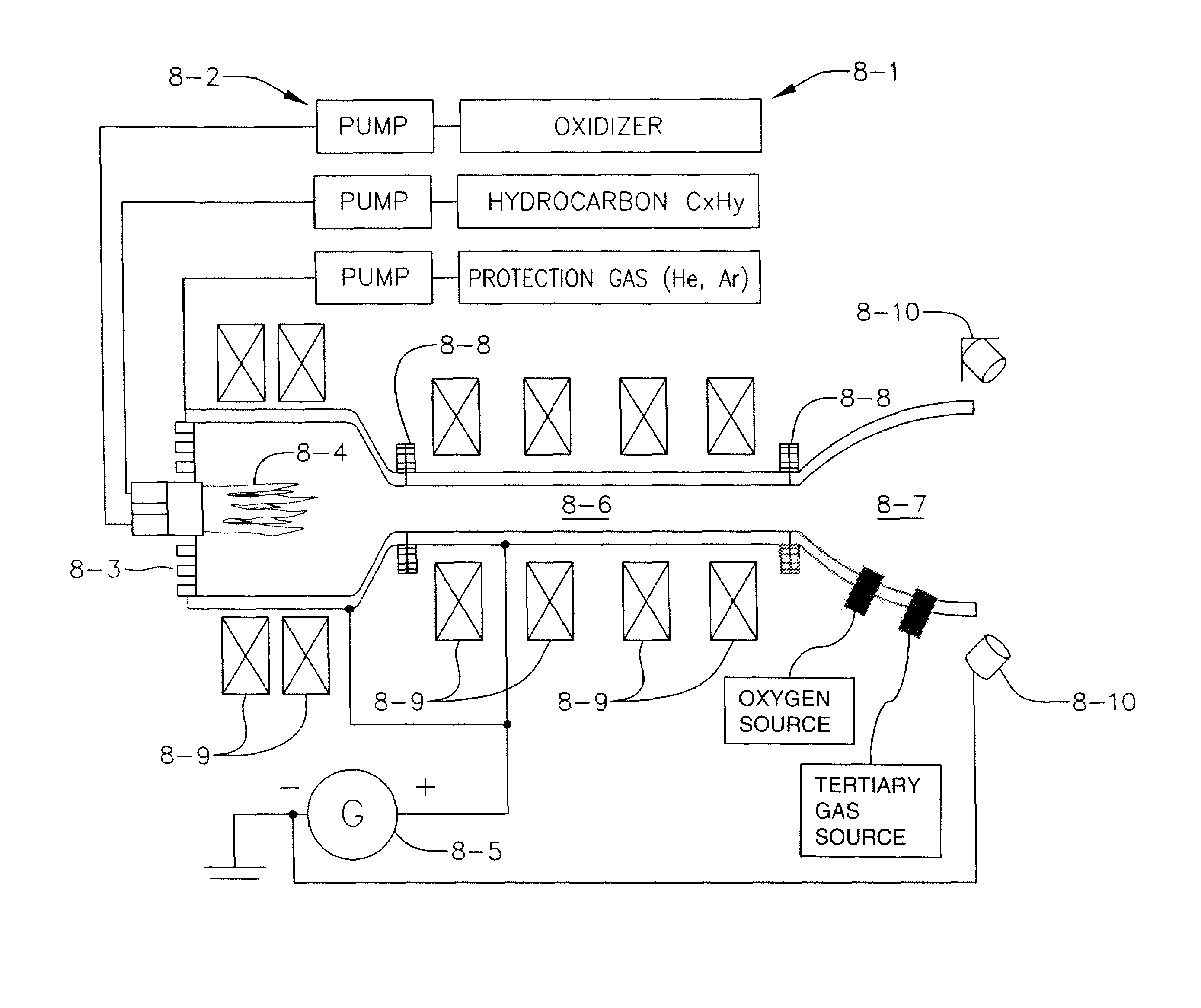
[0094]an acceleration channel (7-1) is shown in FIG. 7b. Segments (7-6) of the acceleration channel are electrically disjointed by isolators (7-7) and arranged symmetrically along a central axis. In this embodiment all segments are connected to one generator, but it is also possible to provide several generators without limiting the invention. The generators could be joined with single segments or even segment groups. In a further embodiment of this invention permanent magnets or electromagnets could be arranged around the acceleration channel (7-1). The magnets are not shown in FIG. 7b.

[0095]A further embodiment of the acceleration channel is shown in FIG. 7c. The segments (7-6) of the acceleration channel (7-1) have a telescopic movable arrangement. The arrows in FIG. 7c show the mechanical adjustment units schematically. This embodiment allows for the length of the acceleration channel to be adjusted. In addition to telescopic movable arrangements there could be mutual outer or ...

first embodiment

[0110]In a first embodiment, the wall material of the combustion chamber or a collision-sheet are made of a main group, d-block or f-block metal, or an alloy of at least two metals. Due to the extreme heat and abrasion within the plasma-chamber, the metal (or metal alloy) evaporates into the plasma-chamber. Then, ionization and incorporation occurs into rather defined CxHyMez-clusters or CxHyMe1z1Me2z2 . . . -clusters (Me=metal). This approach has the advantage of greater flexibility for the metal composition, and the cooling system (or at least a part of the cooling system) could be saved.

[0111]In a second embodiment, a main group, d-block, or f-block metal (as conventionally defined in the periodic table) can be employed as separate chemical substances, which can be evaporated relatively easy (at T2O) with a relatively low boiling point; metal hydrides with suitable evaporation properties (such as CaH2); suitable metal carbides (such as CaC2); and metal alloys (as for instance wit...


PUM

PropertyMeasurementUnit
temperatureaaaaaaaaaa
diametersaaaaaaaaaa

Abstract

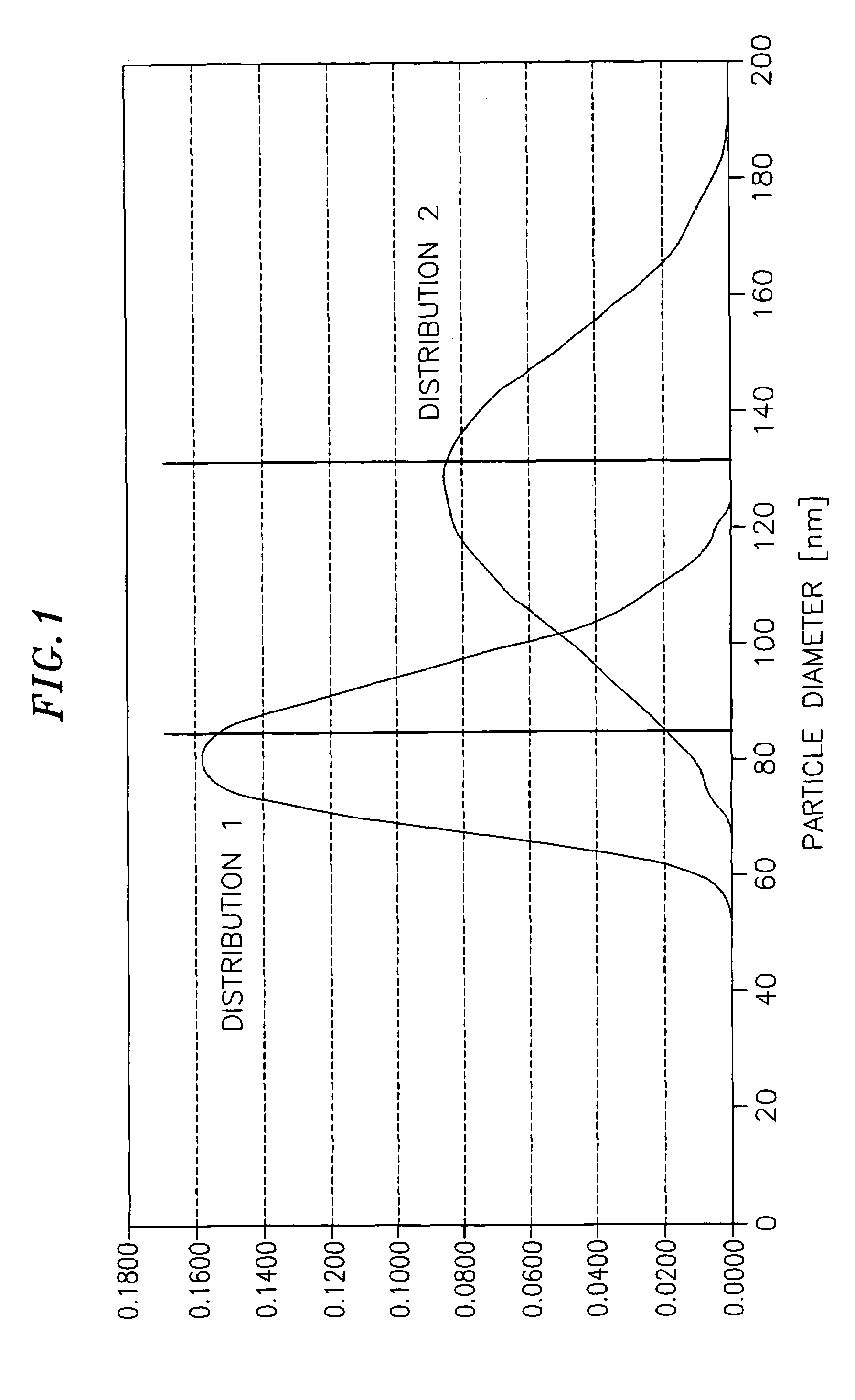
A thermo-chemical nanoparticle generator for the controlled production of nanoparticles, and a method of controllably producing nanoparticles are provided. The combustion of a carbon based propellant under the controlled variation of combustion parameters (temperature, pressure and stoichiometry) allows for the production of ionized nanoparticles of a defined mass. In addition, with the assistance of a high voltage generator a combined ionized gas- / solid particle plasma stream can be produced, which can accelerated in an acceleration tube to high emission velocities allowing for applications of the invention ranging from spacecraft propulsion to plasma welding.

Description

CROSS-REFERENCE TO RELATED APPLICATIONS[0001]The current application claims priority to German Patent Application No. DE 102004014618, filed Mar. 23, 2004, the disclosure of which is incorporated herein by reference.FIELD OF THE INVENTION[0002]This invention generally relates to a device for producing ionized nanoparticles of a defined mass as well as a variable specific impulse.BACKGROUND OF THE INVENTION[0003]The production of ionized particles is well known from the literature, particularly in the field of electrostatic and electro-thermal propulsion systems for space applications.[0004]For example, electrostatic devices follow the functional principle that a gaseous propellant is ionized with the aid of an ionization source. An ion extraction device produces a beam of positive ions out of the existing-plasma. A voltage control unit can be used to adjust the potential of the voltage between the shield electrode and the acceleration electrode to provide a level of variability to t...

Claims


Application Information

Patent Timeline
Patent Type & Authority Patents(United States)
IPC IPC(8): F03H1/00B22F1/16B64G1/40F03H99/00G21D1/00H05B1/00
CPCB22F1/02B22F9/12B23K10/02F03H1/0093B22F1/0018B22F2999/00B22F2202/13B22F1/16B22F1/054
Inventor BOSSMANN, STEFAN H.BORA, NORBERT
Owner BOSSMANN STEFAN H
Learn More