
Method and apparatus for measuring electro-physiological activity

a technology of electrophysiological activity and measuring method, applied in the field of electrophysiological activity, can solve the problems of time-consuming and laborious measurement process, difficult attachment and removal, and inconvenient patient care, and achieve the effect of improving performan

Inactive Publication Date: 2008-11-04
SRICO
View PDF16 Cites 25 Cited by
  • Summary
  • Abstract
  • Description
  • Claims
  • Application Information

AI Technical Summary

Benefits of technology

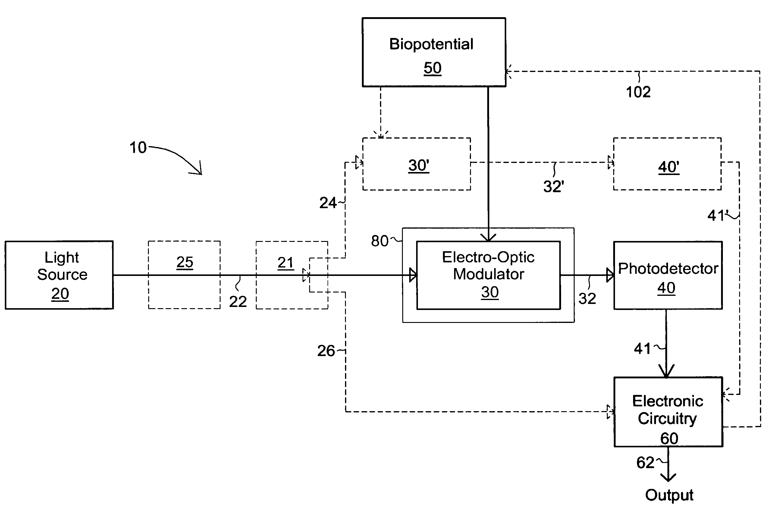
"The present invention is a high impedance optical-based electrode that features a resistance to electrical current flow of more than 1×10¹⁴ ohms. This is achieved by using interferometers that take advantage of the high-frequencies of light in the tera-hertz range. The electrode operates with a resistance to electrical current flow of more than 1×10⁹ ohms. The invention also features a stable housing to protect the electro-optic material from environmental factors that could change its sensitivity. The invention improves the monitoring of various electrical signals by using a light interferometer that provides a modulating light output proportional to the bio-potential being measured. The invention also includes various electrical circuits for improving performance, such as a super low-noise optical receiver circuit, an amplifier circuit, a DC transient suppression circuit, a filtering circuit, and an automatic gain control circuit using an out-of-range pilot tone."

Problems solved by technology

If body hair is present, however, attachment and removal can be problematic.
1) The electrodes are often made of materials such as gold or silver preventing routine disposal. This means that the electrodes must be cleaned before and after use by each patient.
2) The patients' scalp must be cleaned using a relatively strong solvent, such as acetone, and mildly abraded prior to application of the cup-shaped electrode filled with electrolyte paste.
3) New electrolyte gel must be applied manually to the electrode prior to attachment for each new patient.
4) Pressure must be applied to the gel-filled electrode-cup assembly to cause adherence to the head. This process is often uncomfortable for the patient.
5) The contact resistance of the electrode to the scalp must often be measured to insure it is less than 1000 ohms otherwise noisy recordings are obtained. This measurement process is time consuming and tedious.
6) During use, the electrolyte gel tends to harden and stick to the hair of the patient. Removal of the electrodes and remnants of the gel from the hair takes some time and effort with much discomfort to the patient.
During use, the electrodes often became dislodged requiring re-attachment.
1) A trained technical staff person is normally required to attach the electrodes. Often this technician is not available at all times, so the clinician cannot depend on obtaining the desired EEG data.
2) There is an additional cost factor associated with using trained staff and the current medical reimbursement policies tend to encourage minimal use of trained staff in the hospital environment.
3) The attachment protocol takes a considerable amount of time especially when multiple electrodes are required.
4) The ordeal is difficult and tedious for the patient.
Because of the cost and inconvenience of applying EEG electrodes, it is difficult (if not impossible) to use the EEG for routine patient monitoring.
Currently, however, not many patients are monitored (except some children) while they are in the MRI using EEG and / or ECG instrumentation.
Basically, the MRI and EEG / ECG equipment are not compatible.
Such situations can be fatal if the current induced is sufficiently large.
The presence of equipment near the MRI machine can also interfere with the diagnostic quality of the MRI images themselves by causing distortions in the MRI output.
Also, the radio-frequency (RF) fields of the MRI machine can corrupt the weak signals being recorded by ECG equipment and especially even weaker signals associated with EEG instruments.

Method used


Image

  • Method and apparatus for measuring electro-physiological activity
  • Method and apparatus for measuring electro-physiological activity
  • Method and apparatus for measuring electro-physiological activity

Examples


example i

[0127]Conventional practice for attaining ECG signals requires removal of clothing as well as application of an electrolyte gel. In the present invention, ECG recordings are taken without removal of clothing thereby eliminating the need for electrolyte gel and also providing optimum comfort to the patient undergoing testing. The ECG is measured by placing the electro-optic modulator 30 on the heart (over the clothes) in the left leg / right ventricle position as seen in FIG. 7. FIG. 28 shows the equivalent impedance of the device 30 with respect to the heart placement. The shunting resistor 113 is shown to have a value of 100 GW thereby increasing the DC stability of the device 30. Since the ECG signal coupling can be capacitive in nature, the signal may also be detected without the use of conducting silicon and with a simple metal electrode, or disk for contact with the skin. A notch filter (not shown) was used in order to block the effects of 60 Hz environmental fields on the ECG wa...

example ii

[0129]Traces taken with the electro-optic module of the current invention of EEG activity is very similar to low impedance electrode data. The EEG pattern is typical of a normal subject showing the eyes open and closed response. As an example, a single electrode (E5 GH Astro-Medical Inc. West Warwick, R.I.), and an electro-optic module of the present invention were placed on the occipital lobe 110 in order to measure the brain's alpha wave activity (FIG. 30). FIG. 31 shows the equivalent impedance of the EEG with respect to the device 30. The shunting resistor 113 is shown having a value of 1 GW and thus improves the DC stability of the device 30. A reference electrode 102, such as the Life-Patch, was attached to the ear for grounding purposes. The standard EEG electrode required abrading the patients scalp with acetone whereas the electrode of the current invention 30 required no abrasion techniques. Colloid was applied to the standard electrode in order to get the electrode to sti...


PUM


Abstract

An electro-optic modulator modulates light in response to a life-form bio-potential to provide a bio-potential modulated light output. Modulation can be carried out as a result of capacitive coupling with the bio-potential. Phase, polarization, and intensity light modulation can be used. The light output can then be converted to electronic form for further processing. An optical power splitter is used to split light into multiple portions that are converted to electrical form. A pilot tone is used to achieve high sensitivity and synchronize multiple electro-optic modulators while phase modulation can be used to reduce noise in the bio-potential signal. Low-coherent light may be used as the light source. A housing is provided that can be hermetically-sealed and provided with electro-magnetic shielding.

Description

CROSS REFERENCE TO RELATED APPLICATION[0001]This application is a continuation of U.S. patent application Ser. No. 09 / 898,402, filed on Jul. 3, 2001 and issued as U.S. Pat. No. 6,871,084 on Mar. 22, 2005 and claims the benefit of U.S. Provisional Application 60 / 215,918 filed on Jul. 3, 2000 all of which is incorporated by reference as if completely written herein.STATEMENT REGARDING FEDERALLY SPONSORED RESEARCH OR DEVELOPMENT[0002]The U.S. Government has a paid-up license in this invention and the right in limited circumstances to require the patent owner to license others on reasonable terms as provided for by the terms of contract No. DAMBI7-98-C8008 and 8009 awarded by the U.S. Army Medical Research and Material Command.BACKGROUND OF THE INVENTION[0003]1. Field of the Invention[0004]The present invention relates, in general, to electrodes used in the measurement of bio-potential signals produced by living bodies and more particularly to high-impedance electrodes for transferring ...

Claims


Application Information

Patent Timeline
Patent Type & Authority Patents(United States)
IPC IPC(8): A61B5/04A61B5/308
CPCA61B5/0408A61B5/0428A61B5/0478A61B5/25A61B5/30A61B5/291A61B5/31
Inventor KINGSLEY, STUART A.SRIRAM, SRIRAM S.BOIARSKI, ANTHONY A.GANTZ, NORMAN
Owner SRICO
Learn More