Fuel cell life predicting device and fuel cell system

a fuel cell and life prediction technology, applied in the direction of electrochemical generators, instruments, material impedances, etc., can solve the problems that the life of the fuel cell cannot be sufficiently predicted by the related art methods, and the degradation/breakage of the fuel cell occurs suddenly

Inactive Publication Date: 2008-09-09
PANASONIC CORP
View PDF3 Cites 6 Cited by
  • Summary
  • Abstract
  • Description
  • Claims
  • Application Information

AI Technical Summary

Benefits of technology

[0028]On the contrary, the inventors of the present invention had an idea that the degree of degradation / damage of the electrolyte membrane of a fuel cell may be found by analyzing the decomposition product produced by the decomposition reaction of the fuel cell on the basis of the fact that the decomposition product produced by the decomposition reaction of the electrolyte membrane of the fuel cell, if degradated and damaged, is released with the waste material discharged from the fuel cell. The present inventors then paid attention to the measurement of the amount of specific chemical species contained in the waste material discharged from the fuel cell. In other words, the present inventors thought that more accurate life prediction must be attained by focusing on the degradation of the properties of the electrolyte membrane. Eventually, the present inventors came up with an idea that the life of a fuel cell is predicted by making the use of the measured amount of specific chemical species such as fluoride ion among decomposition products rather than by analyzing all the decomposition products of the fuel cell. The present inventors actually established a method capable of sufficiently accurately predicting the life of a fuel cell even if the degradation of the fuel cell suddenly occurs by measuring the amount of specific chemical species or the corresponding electrical conductivity. The present application has been worked out on the basis of this concept.

Problems solved by technology

In the case where the electrolyte membrane degradates and breaks or the like, the degradation / breakage of the fuel cell occurs suddenly.
However, the degradation of the fuel cell cannot be sufficiently predicted by the related art methods.

Method used


Image

  • Fuel cell life predicting device and fuel cell system
  • Fuel cell life predicting device and fuel cell system
  • Fuel cell life predicting device and fuel cell system

Examples


embodiment 1

[0066]The embodiment 1 of the invention will be described below.

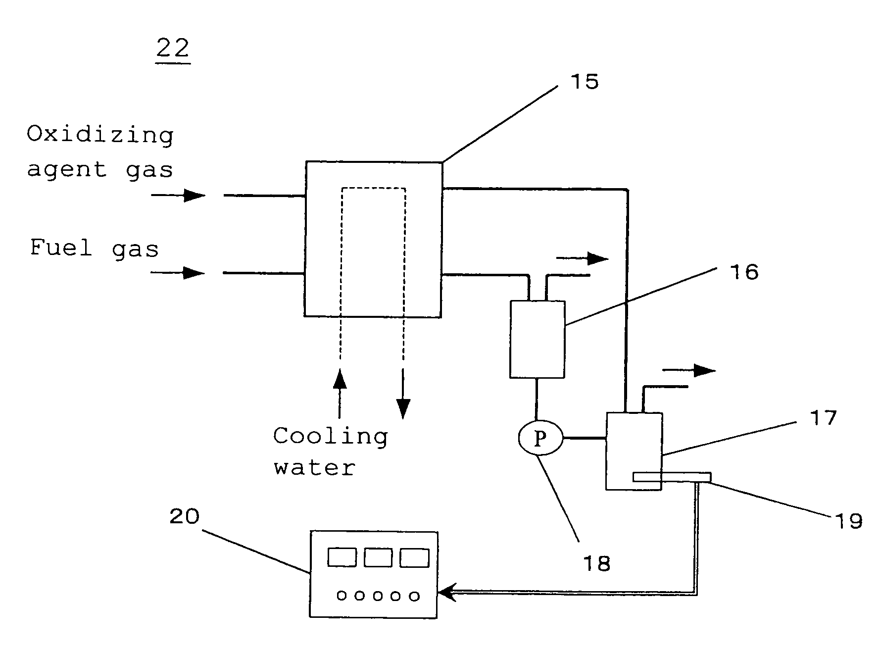
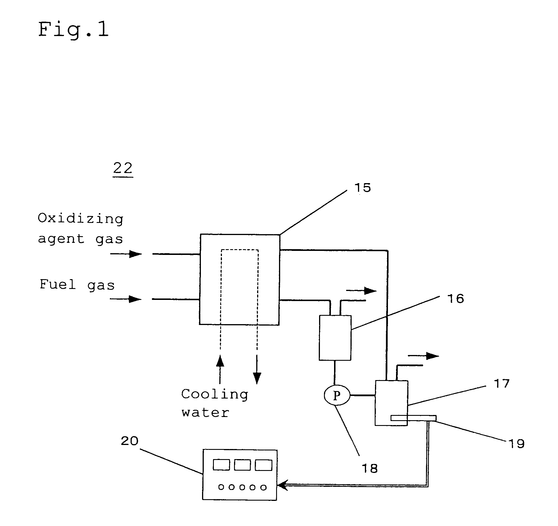
[0067]FIG. 1 illustrates the configuration of a fuel cell system 22 according to the embodiment 1 of the invention.

[0068]The fuel cell system 22 according to the embodiment 1 of the invention comprises a fuel cell 15, an anode drain tank 16, a cathode drain tank 17, a pump 18, an F ion meter 19 and a controlling portion 20.

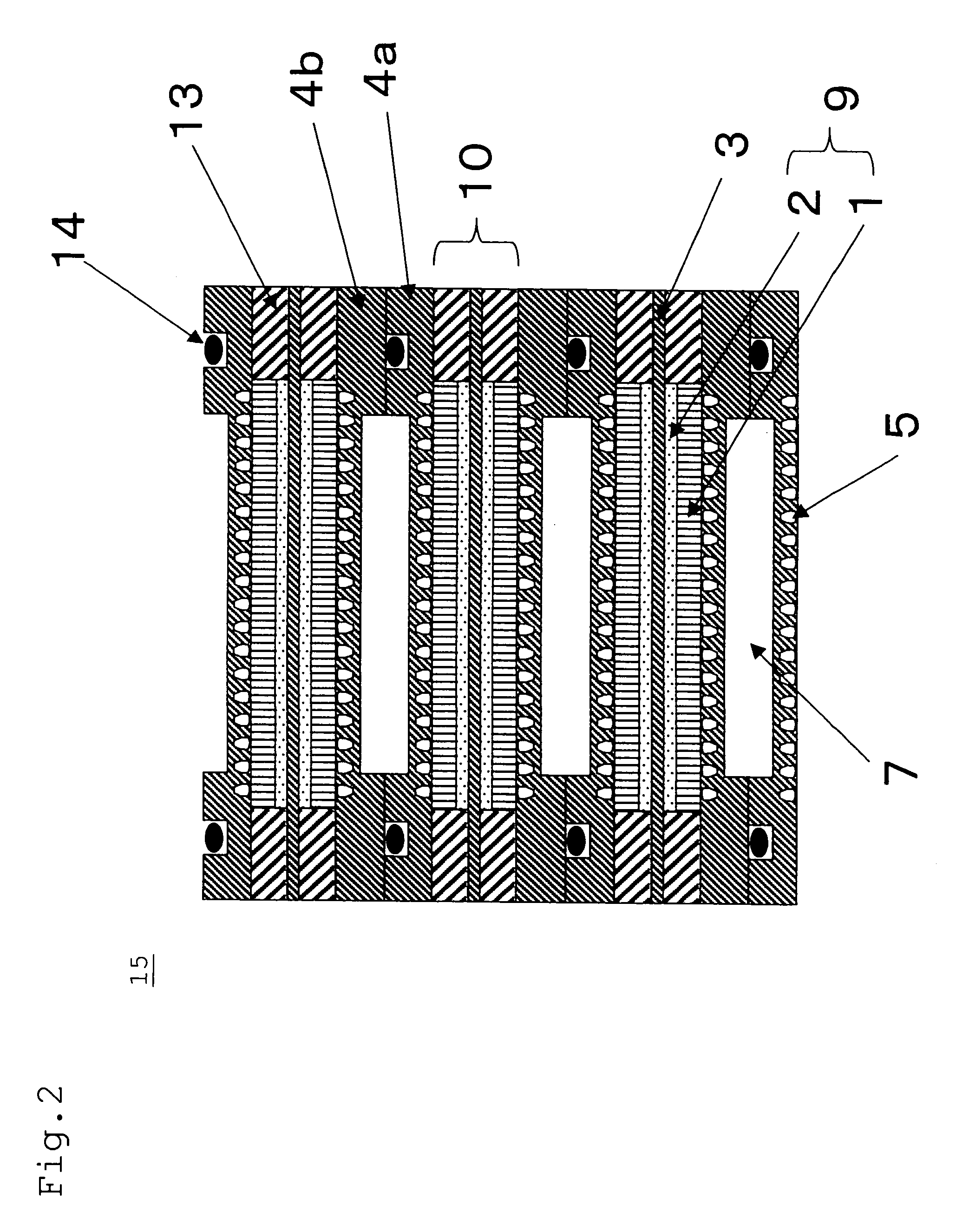
[0069]FIG. 2 is a specific sectional view illustrating the configuration of a polymer electrolyte fuel cell 15 according to the embodiment 1 of the invention. FIG. 2 will be further described later. The anode drain tank 16 is a tank adapted to cause water and water vapor to be released from the waste material contained in the anode waste gas (containing both liquid and gaseous waste materials) discharged from the anode of the fuel cell 15. The cathode drain tank 17 is a tank adapted to cause water and water vapor to be released from the waste material contained in the cathode waste gas (containing bot...

embodiment 2

[0123]The embodiment 2 of the invention will be describe hereinafter.

[0124]FIG. 6 illustrates the configuration of a fuel cell system 23 according to the embodiment 2 of the invention.

[0125]The fuel cell system 23 according to the embodiment 2 of the invention comprises an electrical conductivity meter 21 instead of the F ion meter 19 of the fuel cell system 22 according to the embodiment 1 of the invention.

[0126]The electrical conductivity meter 21 is a unit of measuring the electrical conductivity of the drain water in the cathode drain tank 17.

[0127]The fuel cell system 23 according to the embodiment 2 of the invention is the same as the fuel cell system 22 according to the embodiment 1 of the invention except for the aforementioned configuration.

[0128]The electrical conductivity meter 21 according to the present embodiment is an example of the measuring portion of the invention. The controlling portion 20 according to the present embodiment is an example of the life predicting p...

example 1

[0168]The fuel cell 15 as shown in FIG. 2 was prepared.

[0169]In some detail, an electrode 9 with a catalyst layer comprising a gas diffusion layer 1 was attached to a polymer electrolyte membrane 3 (Nafion film having a thickness of 50 μm, produced by Du Pont Inc.) to prepare MEA 10.

[0170]MEA 10 was then disposed interposed between an air-tight carbon separator 4 and a gas sealing material 13 made of silicon rubber to form an elementary cell. Two units of such an elementary cell were then laminated to obtain a cell constituent unit from which a laminate of fuel cells having the configuration shown in FIG. 2 was then prepared. The total number of elementary cells laminated was 10. A gold-plated collector made of copper, an insulating plate made of an electrical insulating material and an end plate were then provided on the both ends of the laminate in this order to prepare a laminated cell 15.

[0171]The laminated fuel cell thus prepared 15 was then operated with hydrogen gas and air f...


PUM

PropertyMeasurementUnit
thicknessaaaaaaaaaa
temperatureaaaaaaaaaa

Abstract

There are provided measuring units of measuring the amount of fluoride ions in the waste material from a fuel cell which receives a fuel gas and an oxidizing agent gas containing oxygen to undergo electrochemical reaction by which electricity is generated and a life predicting unit of predicting the life of the fuel cell by the use of the amount of fluoride ions thus measured.

Description

BACKGROUND OF THE INVENTION[0001]1. Field of the Invention[0002]The present invention relates to a device of predicting the life of a fuel cell, particularly a polymer electrolyte fuel cell for use in electric supply for portable apparatus, portable electric supply, electric supply for electric car, household cogeneration system, etc. and a fuel cell system.[0003]2. Related Art of the Invention[0004]A polymer electrolyte fuel cell causes the electrochemical reaction of a fuel gas such as hydrogen with an oxidizing agent gas such as air through a gas diffusion electrode to generate electricity. FIG. 13 is a schematic sectional view illustrating an ordinary configuration of such a related art polymer electrolyte fuel cell.[0005]As shown in FIG. 13, the polymer electrolyte fuel cell 120 comprises a gas diffusion layer 101, a catalytic reaction layer 102, a polymer electrolyte membrane 103, a separator 104, a gas flow path 105, a cooling water flow path 107, an electrode 109, MEA 110, a...

Claims


Application Information

Patent Timeline
Patent Type & Authority Patents(United States)
IPC IPC(8): H01M8/04H01M8/10H01M8/06
CPCH01M8/04246H01M8/0447H01M8/04679H01M8/04477H01M8/04156Y02E60/50H01M2008/1095
Inventor YASUMOTO, EIICHIARISAKA, SHINICHISAKAI, OSAMUKASAHARA, HIDEOUNOKI, SHIGEYUKI
Owner PANASONIC CORP
Why Eureka
Try Eureka