
Rotating disk storage device with high rigidity flexible printed circuit board

a flexible printed circuit board and rotating disk technology, applied in the direction of recording information storage, printed circuit non-printed electric components association, instruments, etc., can solve the problems of lead influence on the environment, deformation of reflow furnace, and difficulty in fixing the carriage and the fpc, or the base (an upper surface of the case bottom wall)

Inactive Publication Date: 2008-09-02
WESTERN DIGITAL TECH INC
View PDF7 Cites 2 Cited by
  • Summary
  • Abstract
  • Description
  • Claims
  • Application Information

AI Technical Summary

Benefits of technology

This solution enables the use of lead-free solder while maintaining high rigidity and reliability, preventing malfunction of shock sensors and improving the overall performance and productivity of the magnetic disk drive by allowing a single reflow process without adhesive-related issues.

Problems solved by technology

It has recently been demanded that industrial products adapt themselves to the environment, and the influence of lead on the environment has become an issue.
However, the use of a lead-free solder results in the melting point being in the range of about 220° to 230° C., so that even if a polyether imide [trade name: ULTEM®] having a high heat resistance is used as a synthetic resin, the reinforcing plate when placed into a high-temperature reflow furnace will be deformed, making it difficult to fix the carriage and the FPC, or the base (an upper surface of the case bottom wall) and the FPC, to a satisfactory extent, with a consequent fear of causing various problems related to product reliability and productivity.
Particularly, if the base-FPC fixing is not done to a satisfactory extent, the shock sensor disposed on the FPC will malfunction, which leads to a marked deterioration in performance of the magnetic disk drive.

Method used


Image

  • Rotating disk storage device with high rigidity flexible printed circuit board
  • Rotating disk storage device with high rigidity flexible printed circuit board
  • Rotating disk storage device with high rigidity flexible printed circuit board

Examples


Embodiment Construction

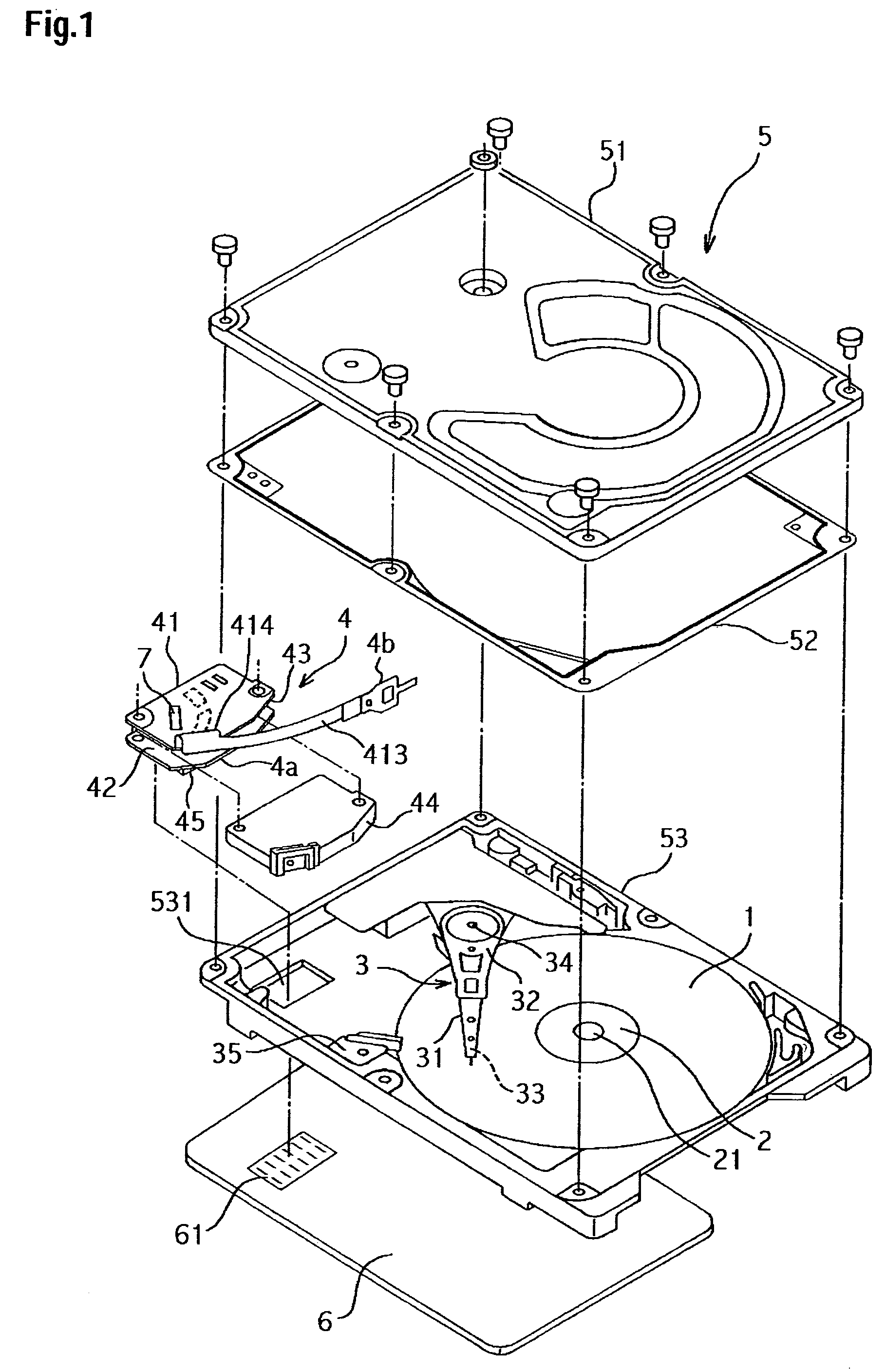
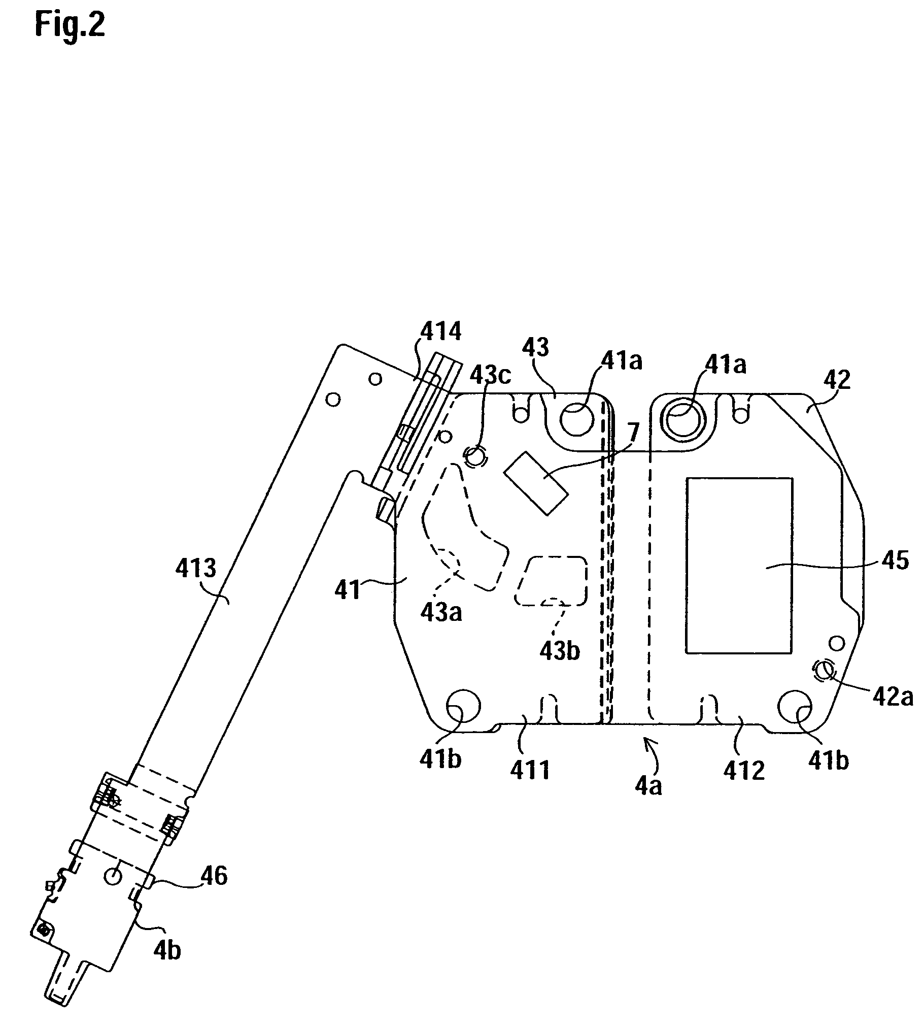
[0030]A rotating disk storage device according to an exemplary embodiment of the present invention will be described hereinbelow with reference to the accompanying drawings. FIG. 1 illustrates a magnetic disk drive in a partially exploded state, FIG. 2 is a developed structural diagram (before bending) of an FPC assembly, FIG. 3 is a developed structural diagram (before bending) showing a wiring pattern formed on the FPC, FIG. 4 is a structural diagram of a first metallic plate and a second metallic plate both fixed to the FPC, and FIG. 5 is a perspective view of reinforcing plate of a synthetic resin as a constituent element of the FPC assembly. In all of the accompanying drawings, the same constituent elements are identified by the same reference numerals.

[0031]In a magnetic disk drive as a rotating disk storage device according to an exemplary embodiment of the present invention, as shown in FIG. 1, a magnetic disk 1 as a rotating disk storage medium, a spindle motor 2, an actuat...


PUM

PropertyMeasurementUnit
melting pointaaaaaaaaaa
temperatureaaaaaaaaaa

Abstract

A flexible printed circuit board using a lead-free solder is to be fixed within a disk enclosure while ensuring a high rigidity. In one embodiment, a rotating disk storage device comprises a flexible printed circuit board (FPC), wherein there is formed a wiring pattern including a signal line for the transmission of a signal of data read by a head in an actuator head suspension assembly (AHSA) and wherein one side end portion is fixed to a base and an opposite side end portion is fixed to the AHSA. A first metallic plate and a second metallic plate are both fixed to one side end portion of the FPC. A connector is disposed in an area where the first metallic plate in the FPC is provided, and connected to the wiring pattern. A shock sensor is disposed in an area where the second metallic plate in the FPC is provided, and connected to the wiring pattern. A reinforcing plate of a synthetic resin is, in an opposed state of the first and second metallic plates fixed to one side end portion of the FPC, held between the opposed faces of both metallic plates and is fixed to the base together with both metallic plates.

Description

CROSS-REFERENCES TO RELATED APPLICATIONS[0001]This application claims priority from Japanese Patent Application No. JP 2003-430189, filed Dec. 25, 2003, the entire disclosure of which is incorporated herein by reference.BACKGROUND OF THE INVENTION[0002]The present invention relates to a rotating disk storage device such as a magnetic disk drive or a magneto-optic disk drive wherein a flexible printed circuit board using a lead-free solder can be fixed within a disk enclosure while retaining a high rigidity.[0003]A magnetic disk drive is generally composed of a head disk assembly (hereinafter referred to as “HDA”) and a printed circuit board attached to the HDA. The HDA is of construction sealed with a disk enclosure in order to accommodate a magnetic disk, an actuator head suspension assembly (“AHSA”), a spindle motor, and an electronic component in a clean air atmosphere. The printed circuit board has an electronic component mounted thereon for controlling the operation of the magn...

Claims


Application Information

Patent Timeline
Patent Type & Authority Patents(United States)
IPC IPC(8): G11B21/02G11B33/12G11B5/55G11B25/04G11B33/14H05K1/18
CPCG11B33/122H05K1/189H05K2201/056H05K3/0064H05K3/0061
Inventor SEKIMOTO, TATSUOHIRAMATSU, TOMOKITAKEMOTO, MOTOJIYUKI, TETSUO
Owner WESTERN DIGITAL TECH INC
Learn More